Manufacturing method and package structure of optical fiber stripper

A technology of packaging structure and manufacturing method, applied in the field of laser technology and optical fiber, can solve the problems of burnout of optical fiber stripper, damage of optical fiber stripper, leakage of laser light, etc., to increase absorption area and absorption efficiency, improve stability and Work efficiency and uniform heat distribution

Inactive Publication Date: 2019-03-29
CELOX PHOTONICS TECH CO LTD
View PDF6 Cites 4 Cited by
  • Summary
  • Abstract
  • Description
  • Claims
  • Application Information

AI Technical Summary

Problems solved by technology

Secondly, the organic glue with a high refractive index is an organic polymer. If it works at high temperature for a long time, the organic glue will deteriorate, resulting in increased light absorption and a further rise in temperature, which may eventually cause damage to the optical fiber stripper and seriously affect the high-quality optical fiber. Power Fiber Laser Stability
[0004] In addition, the existing technology only processes the optical fiber to make a fiber stripper, so that the cladding light can leak out, but does not effectively package the fiber stripper
Since the fiber stripper is used to strip the cladding light, a large amount of laser light will leak out from the surface of the fiber stripper, especially as the output power of the fiber laser increases, the laser energy density and temperature on the surface of the fiber stripper are very high , generate a lot of heat, once it reaches the melting point, it is easy to burn out the fiber stripper itself
A large amount of leaked laser light diffuses in the fiber laser optical path module, which can easily cause optical components to be damaged by the leaked laser light
In addition, since the optical fiber stripper accumulates a large amount of energy, the temperature is very high. If it cannot be disposed of properly, the heat will spread to the optical module of the fiber laser, causing the temperature of the optical module to rise and affecting the stability of the fiber laser system.

Method used


Image

  • Manufacturing method and package structure of optical fiber stripper
  • Manufacturing method and package structure of optical fiber stripper
  • Manufacturing method and package structure of optical fiber stripper

Examples


Embodiment Construction

[0023] In order to understand the technical content of the present invention more clearly, the following examples are given in detail, the purpose of which is only to better understand the content of the present invention but not to limit the protection scope of the present invention.

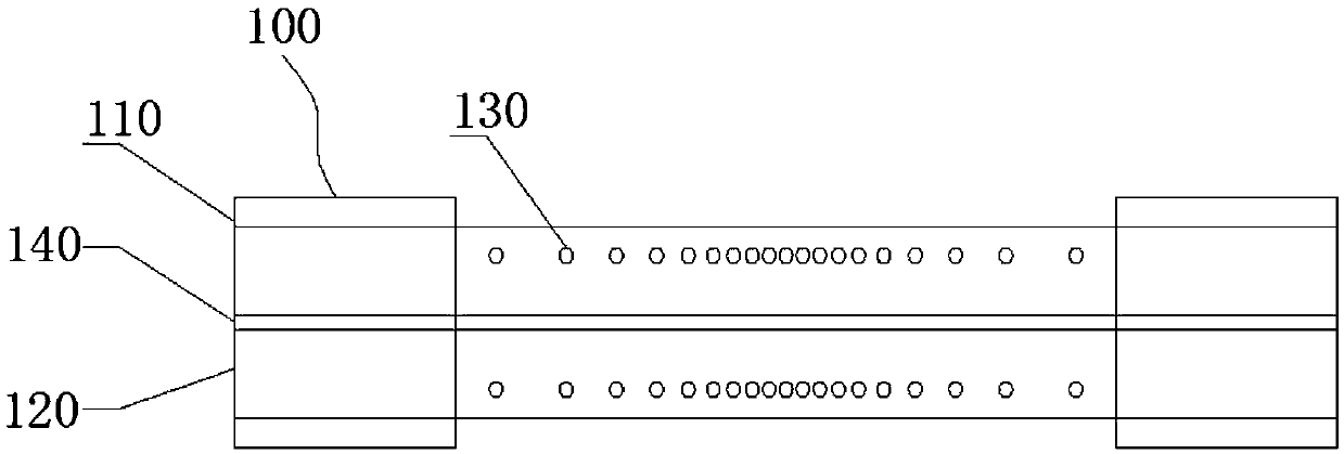
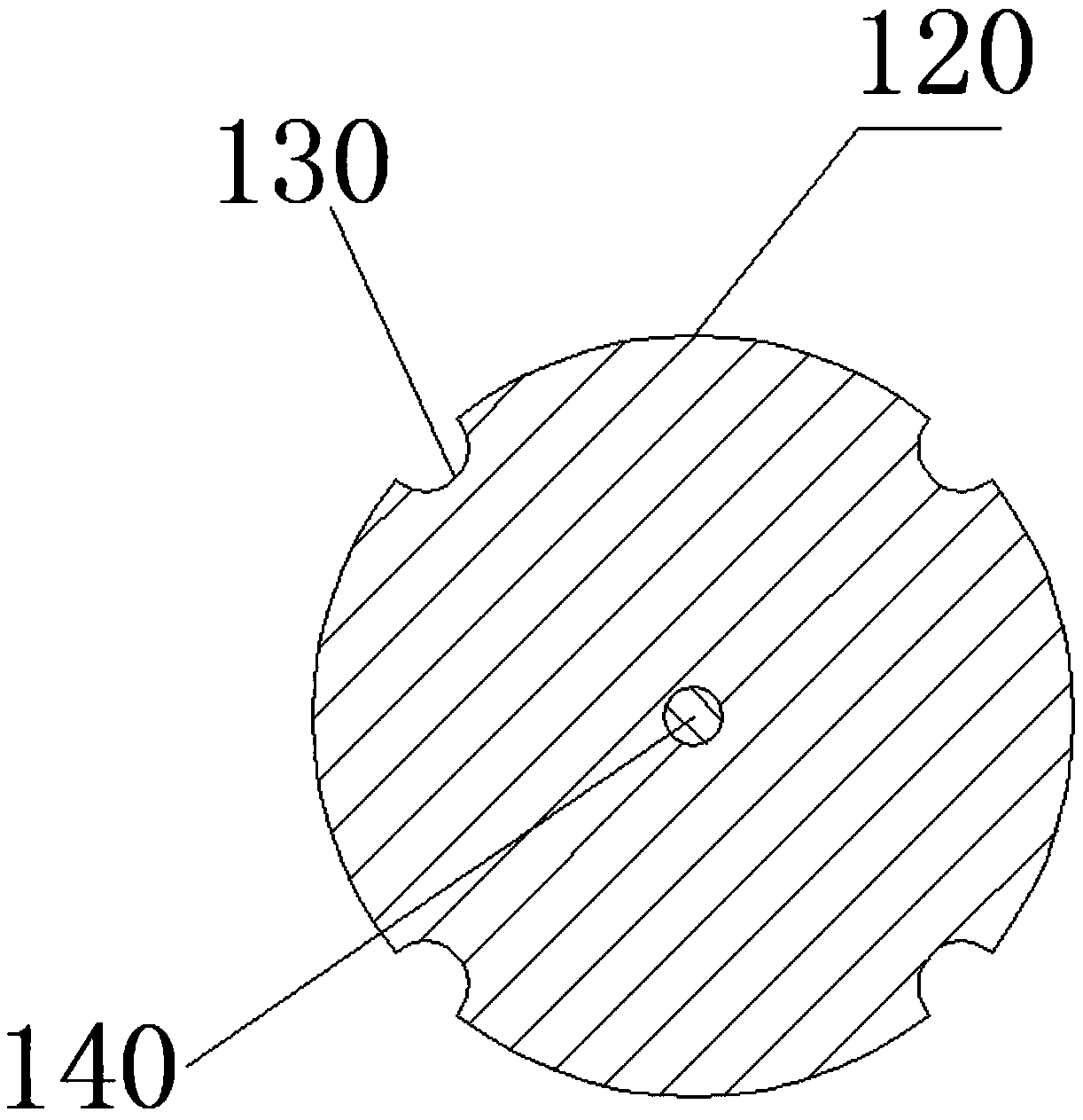
[0024] The manufacturing method of the optical fiber mode stripper of the present invention is to use a laser to etch the surface of the inner cladding 120 of the double-clad passive optical fiber 100 from which the outer cladding 110 has been stripped, and to form at least one row on the inner cladding of the double-clad passive optical fiber. For the plurality of holes 130 arranged at intervals along the axial direction, the etching density of the plurality of holes gradually decreases from the middle to both ends, and the etching depth of the plurality of holes gradually becomes shallower from the middle to both ends. In this way, by improving the manufacturing method of the traditional optic...


PUM


Abstract

The invention provides an optical fiber stripper, a manufacturing method and package structure of the optical fiber stripper. The optical fiber stripper has the advantages such as high stripping efficiency, high withstand power, uniform temperature distribution, long service life, high stability and the like. The package structure of the optical fiber stripper is characterized in that: the opticalfiber stripper is placed in a glass tube to provide preliminary package protection for the optical fiber stripper; and then the glass tube is arranged in an accommodating cavity surrounded by a heatconducting cover plate and a heat conducting bottom plate to perform thermal conductive packaging on the optical fiber stripper; therefore, on one hand, the package structure is conveniently installedon a water-cooled plate of an external water-cooling device, the heat emitted by the optical fiber stripper is uniformly transmitted to the water-cooled plate, and then the heat is taken away by thewater-cooling device; on the other hand, the thermal conductive packaging of the optical fiber stripper can prevent the stripped light from leaking into an optical path module; therefore, the damage of the stripped light to the optical path is avoided, the stability and working efficiency of the optical fiber stripper is greatly improved, and the stability of an entire optical fiber laser system is maintained.

Description

technical field [0001] The invention relates to the fields of laser technology and optical fiber technology, in particular to a method for manufacturing an optical fiber mold stripper and its packaging structure. Background technique [0002] Fiber stripper CPS is an important part of fiber laser, used to strip the laser in the inner cladding of the fiber. The pump source LD couples the pump light into the inner cladding of the active fiber through the pump beam combiner, provides energy for the active fiber, generates signal light in the fiber core, and then passes through the resonator feedback mode selection amplification, and then outputs it. However, due to the limited length of the active fiber, the pump light in the cladding cannot be completely absorbed, and part of the pump light in the cladding exists in the form of helical light. Therefore, the cladding contains pump light. In addition, due to the imperfection of the fiber splicing and the defects of the fiber it...

Claims


Application Information

Patent Timeline
Patent Type & Authority Applications(China)
IPC IPC(8): G02B6/245H01S3/067H01S3/04H01S3/042
CPCH01S3/0405H01S3/0407H01S3/042H01S3/06733G02B6/245
Inventor 植田宪一卓壮贺晓宁梅红松
Owner CELOX PHOTONICS TECH CO LTD
Why Eureka
Try Eureka