Light intensity transmission equation-based phase contrast and differential interference contrast micro-imaging method

A light intensity transmission equation and differential interference technology, applied in the field of phase contrast and differential interference phase contrast microscopic imaging, can solve the problems of limited image acquisition frame rate by refresh rate, expensive spatial light modulator, complex experimental equipment, etc. Achieve the effect of not strict working environment requirements, simple structure, and guaranteed image quality

Active Publication Date: 2019-04-05
NANJING UNIV OF SCI & TECH
View PDF9 Cites 12 Cited by
  • Summary
  • Abstract
  • Description
  • Claims
  • Application Information

AI Technical Summary

Problems solved by technology

However, this method only supports qualitative analysis of phase images, and complex experimental devices are required: two sets of polarizers and polarization beam splitters (Wollaston prism or Nomarski prism)
In 2012, Zeng Shaoqun of Huazhong University of Science and Technology proposed a super-resolution differential interference phase contrast microscopic imaging system and microscopic imaging method (CN102998789A), which solved the problem of low imaging contrast in scattered light imaging under structured light illumination, thus realizing the imaging of untreated High-contrast super-resolution imaging of any processed biological sample
However, the spatial light modulator used is expensive, and its refresh rate limits the frame rate of image acquisition, so it cannot be applied to differential interference contrast imaging in high-speed changing processes. In addition, the polarization state of light affects the spatial light modulator's response to light. Modulation problem

Method used


Image

  • Light intensity transmission equation-based phase contrast and differential interference contrast micro-imaging method
  • Light intensity transmission equation-based phase contrast and differential interference contrast micro-imaging method
  • Light intensity transmission equation-based phase contrast and differential interference contrast micro-imaging method

Examples


Embodiment Construction

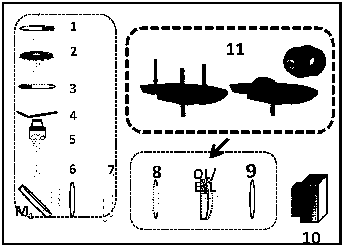
[0015] combine figure 1 , the present invention is based on the microscopic imaging system that possesses adjustable lens module and standard 4F relay system, and the actual hardware platform of this imaging system is an inverted Olympus IX71 type microscope (by figure 1The condenser lens 1, the aperture stop 2, the condenser lens 3, the objective lens 5, and the imaging tube lens 6 are composed). The microscope is equipped with an Olympus camera 10 (Olympus UC50, resolution 2588pixels×1960pixels, 3.4μm / pixel) for image acquisition and an electronically controlled zoom lens (EL-C-10-30-VISLD, OptotuneAG) module 11 for accurate zoom. This system is controlled by software through the USB interface, and ensures the synchronism between the acquisition of the camera 10 and the zooming of the electronically controlled zoom lens module 11 in the direction (z-axis) perpendicular to the focal plane. The image stack is captured by the camera 10 after passing through a long working dis...


PUM


Abstract

The invention discloses a light intensity transmission equation-based phase contrast and differential interference contrast micro-imaging method. According to the method, three intensity images are firstly acquired along an optical axis; a light intensity transmission equation is solved by utilizing deconvolution so as to obtain a quantitative phase diagram; a light intensity diagram under an imaging mode is obtained according to a differential interference contrast imaging principle; and finally, a corresponding phase transfer function is solved according to a phase contrast imaging principleso as to obtain a light intensity diagram under the imaging mode. The method is capable of endowing bright field microscopes with ability of realizing phase contrast and differential interference contrast imaging under the premise of not carrying out complicated transformation on traditional bright field microscopes, namely, realizing same imaging effect with the phase contrast microscopes and differential interference contrast microscopies which are high in cost, complicated in structures and strict in environment condition requirement at the advantages of being quantitative, high in speed,low in cost, simple in structure and less in external interference through a phase contrast and differential interference contrast algorithm by using a common traditional bright field microscope without adding any complicated device.

Description

technical field [0001] The invention belongs to optical microscopic measurement and imaging technology, in particular to a microscopic imaging method based on phase contrast and differential interference phase contrast based on light intensity transmission equation. Background technique [0002] In the field of biomedical imaging microscopy, most samples are phase objects—uniform distributions of amplitude transmission and non-uniform distributions of refractive index or thickness. Therefore, when a light wave passes through a phase object, the wavelength and amplitude change little, but the phase changes greatly (Schmalz J A, Gureyev T E, Paganin D M, et al. Phase retrieval using radiation and matter-wave fields: Validity of Teague's method for solution of the transport -of-intensity equation[J].Physical review A,2011,84(2):023808.). But the human eye and optical detectors cannot observe this phase difference, which carries important information. To solve this problem, th...

Claims


Application Information

Patent Timeline
Patent Type & Authority Applications(China)
IPC IPC(8): G02B21/36G06F17/11G06T11/00
CPCG02B21/367G06F17/11G06T11/00G02B21/14G02B21/365G02B27/126H04N23/56
Inventor 左超卢林芃陈钱孙佳嵩范瑶李加基
Owner NANJING UNIV OF SCI & TECH
Why Eureka
Try Eureka