Elastic-rigid coupling regulating and controlling aluminum alloy sheet electron beam welding stress deformation fixture

A technology of electron beam welding and rigid coupling, which is applied in the direction of electron beam welding equipment, welding equipment, welding equipment, etc., can solve problems such as damage, crack defects on the surface of test pieces, and achieve the effect of avoiding large deformation and avoiding damage

Inactive Publication Date: 2019-04-12
HARBIN INST OF TECH
View PDF6 Cites 2 Cited by
  • Summary
  • Abstract
  • Description
  • Claims
  • Application Information

AI Technical Summary

Problems solved by technology

[0003] The present invention provides an elastic-rigid coupling to control the electron beam welding stress of aluminum alloy sheets in order to solve the problems of cr

Method used


Image

  • Elastic-rigid coupling regulating and controlling aluminum alloy sheet electron beam welding stress deformation fixture
  • Elastic-rigid coupling regulating and controlling aluminum alloy sheet electron beam welding stress deformation fixture
  • Elastic-rigid coupling regulating and controlling aluminum alloy sheet electron beam welding stress deformation fixture

Examples


specific Embodiment approach 1

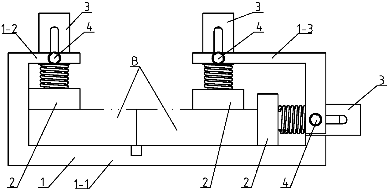
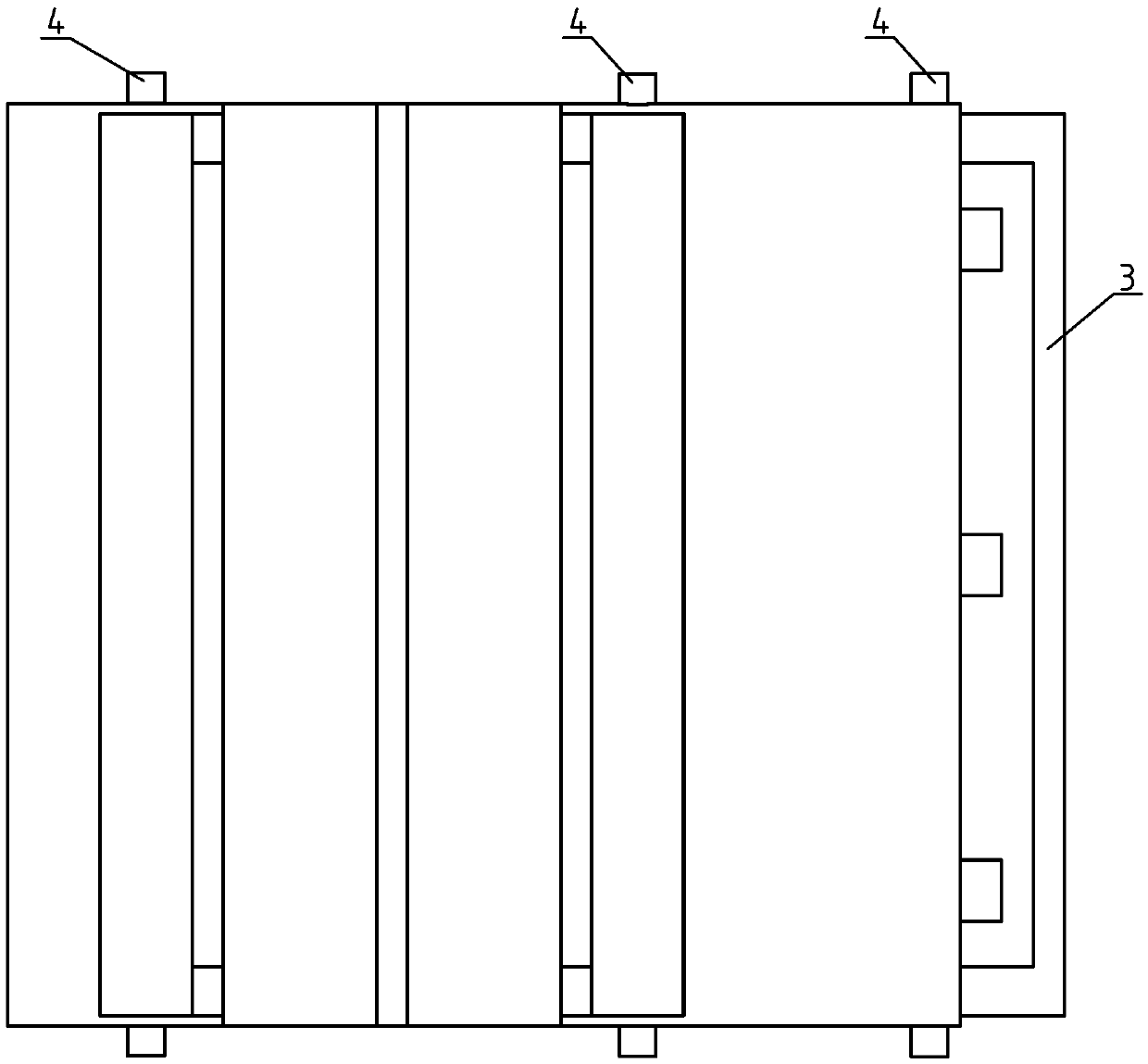
[0023] Specific implementation mode one: combine Figure 1 ~ Figure 4 Describe this embodiment, this embodiment is elastic-rigid coupling adjustment plate electron beam welding stress deformation clamp, which includes a clamp shell 1, three restraint devices 2, three restraint baffles 3 and three connection elements 4;

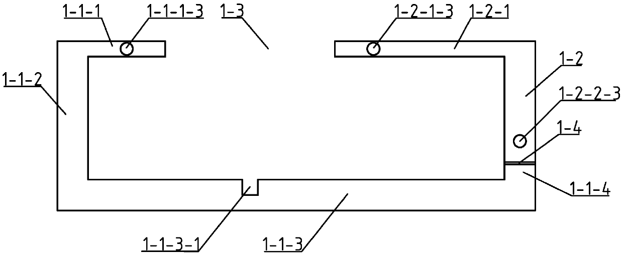
[0024] The fixture shell 1 includes a fixed shell 1-1 and a movable shell 1-2, the movable shell 1-2 and the fixed shell 1-1 form a rectangular frame, the upper end of the rectangular frame is provided with an opening 1-3, the movable shell 1-2 is connected with the fixed shell 1-1 There is a distance (1-4) at the contact point of the fixed shell 1-1, and the distance 1-4 is 1 mm to 2 mm;

[0025] The two ends of the left upper end plate 1-1-1 of the fixed shell 1-1 are respectively provided with textured clamps A, and the left upper end plate 1-1-1 is provided with several left restraining head installation holes 1-1-1 -2, several left restraining head insta...

specific Embodiment approach 2

[0044] Specific implementation mode two: combination Figure 5 Describe this embodiment, the constraining device 2 of this embodiment is composed of a base plate 2-1, several constraining heads 2-2 and several high-strength springs 2-3, and several constraining heads 2-2 are arranged vertically on the base plate 2-2. 1, a high-strength spring 2-3 is set on each constraint head 2-2. The high-strength springs 2-3 are divided into two types: horizontal and vertical, of which there are 3 in the horizontal direction and 6 in the vertical direction, totaling 9. The natural length L of the spring is 25.5mm-60.3mm, the maximum shrinkage △L=10mm, the elastic coefficient K=125N / mm, and the maximum elastic force F=K×△L=125×10=1250N. The maximum force F available in the horizontal direction max It is determined by the maximum shrinkage of the spring (when the length, width and height of the fixture are 150mm×155mm×55mm, and when welding an aluminum plate with a thickness of 100mm×50mm×5...

specific Embodiment approach 3

[0045] Specific implementation mode three: combination image 3 To illustrate this embodiment, the upper end surface of the lower plate 1-1-3 of the fixed housing 1-1 of this embodiment is provided with a groove 1-1-3-1, and the size of the groove 1-1-3-1 is 5mm ×5mm, the groove 2-1-1 can prevent the electron beam from penetrating the sample and acting on the fixture, and protect the fixture bottom plate 2-1. Other components and connections are the same as those in the second embodiment.


PUM

PropertyMeasurementUnit
Natural lengthaaaaaaaaaa
Elastic coefficientaaaaaaaaaa

Abstract

The invention discloses an elastic-rigid coupling regulating and controlling aluminum alloy sheet electron beam welding stress deformation fixture. The problems of crack defect caused by large residual stress caused during rigid constraint and damage to the surface of a test piece caused by point constraint in the welding process are solved. The fixture comprises a fixture shell, three constraintdevices, three constraint baffles and three connecting elements. The three constraint devices are all arranged in the fixture shell, constraint heads arranged on the inner side of an upper end plate on the left side penetrate through left side constraint head mounting holes, constraint heads arranged on the inner side of an upper end plate on the right side penetrate through right side constrainthead mounting holes, and constraint heads arranged on the inner side of a right vertical plate penetrate through lower mounting holes; a constraint baffle is arranged on the outside of each row of constraint heads, the two ends of the constraint baffles are separately arranged in corresponding roughening clamping openings, the constraint baffles are connected with the fixture shell through the connecting elements, and gap of 3mm-8mm are arranged between the constraint baffles and the constraint heads. The elastic-rigid coupling regulating and controlling aluminum alloy sheet electron beam welding stress deformation fixture is used for regulating and controlling the deformation of the plate welding stress.

Description

technical field [0001] The invention relates to a welding jig, in particular to an elastic-rigid coupling regulation and control stress deformation jig for electron beam welding of an aluminum alloy thin plate. Background technique [0002] Welding is the most common processing method for joining two or more metal parts into a component, and the resulting component is usually very strong in all directions. During the welding process of the sample, the weld metal is melted by heat, cooled and solidified, thermal stress, phase change stress, processing stress, etc. exceed the yield limit, and the welding deformation of the test piece is unbalanced, so that the weldment after cooling The stress that cannot be eliminated is left, thus forming the residual welding stress. At the same time, under the action of welding residual stress, the sample produced welding deformation. The welding residual stress of the test piece has an adverse effect on the service performance of the tes...

Claims


Application Information

Patent Timeline
IPC IPC(8): B23K15/00B23K31/00B23K37/04B23K101/18
CPCB23K15/0013B23K31/003B23K37/0443
Inventor 陈国庆柳峻鹏树西尹乾兴张戈张秉刚冯吉才
Owner HARBIN INST OF TECH
Why Eureka
Try Eureka