
A biomass pyrolysis gasification system and its application

A technology of pyrolysis gasification and biomass, applied in gasification process, manufacture of combustible gas, petroleum industry, etc. The effect of reducing the gasification temperature, simplifying the raw material pretreatment process, and improving the gasification efficiency

Active Publication Date: 2020-05-19
HUAZHONG UNIV OF SCI & TECH
View PDF9 Cites 2 Cited by
  • Summary
  • Abstract
  • Description
  • Claims
  • Application Information

AI Technical Summary

Problems solved by technology

However, the existing biomass gasification technology directly applied to the co-combustion of coal-fired boilers still has certain limitations. The problem of unstable combustion; while the calorific value of the gas produced by pyrolysis and gasification is high, but the gasification efficiency is low, and external energy supply is required

Method used


Image

  • A biomass pyrolysis gasification system and its application
  • A biomass pyrolysis gasification system and its application
  • A biomass pyrolysis gasification system and its application

Examples


Embodiment 1

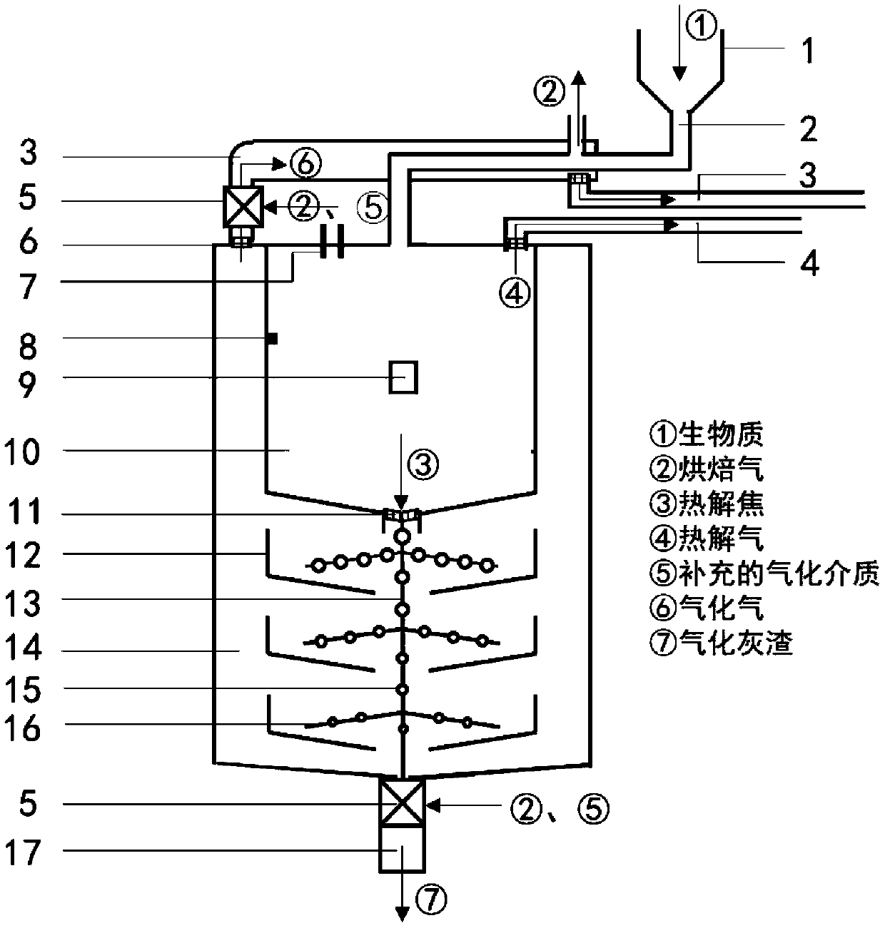
[0039] Under the guidance of the screw feeding device, the preliminarily treated biomass raw material reaches the feed inlet at the upper end of the pyrolysis chamber from the silo, during which the biomass raw material undergoes low-temperature roasting and releases H 2 O.CO 2 small molecule gas; the torrefied biomass raw material is decomposed into pyrolysis coke and pyrolysis gas with higher comprehensive calorific value in the pyrolysis chamber; pyrolysis coke exits from the lower end of the pyrolysis chamber and slowly passes through the gasification chamber , the gasification reaction is carried out under the action of the gasification medium; the gasification gas and pyrolysis gas enter the coal-fired boiler under the guidance of their own dedicated pipelines; the gasification ash enters the ash collector after exchanging heat with the gasification medium.

[0040] When the coupled coal-fired boiler is a fluidized bed boiler 20, the pyrolysis gas and gasification gas ar...

Embodiment 2

[0042] In the biomass pyrolysis gasification system, the operation mode is consistent with that of Example 1.

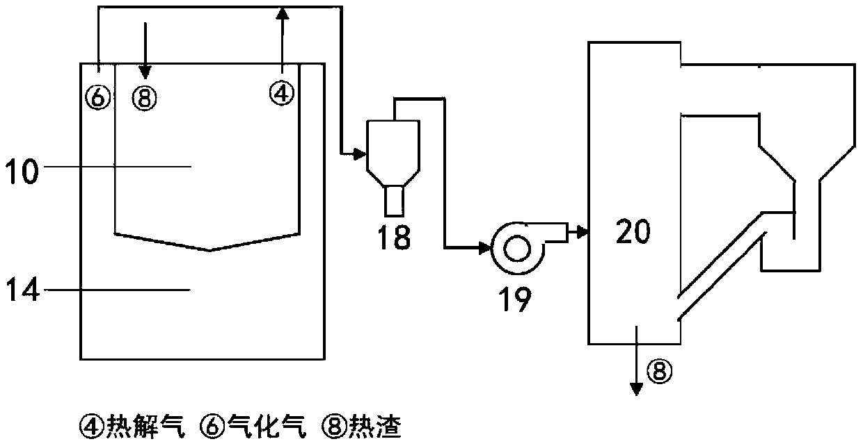
[0043] The pyrolysis gas sent from the pyrolysis gas delivery pipeline 4 of the biomass pyrolysis gasification system is sent to the upper part of the coal-fired boiler 21 through the booster fan 19, so as to promote the reburning of the coal-fired boiler and reduce the NOx emission of the coal-fired boiler; The gasification gas sent from the gasification gas delivery pipeline 3 of the biomass pyrolysis gasification system is separately sent to the lower part of the coal-fired boiler through the gas-solid separator 18 to promote coal combustion. In the case of heat transfer, the gas-solid separator returns part of the separated gasification gas to the burner in the pyrolysis chamber to burn supplementary heat, such as Figure 4 shown.

Embodiment 3

[0045] In the biomass pyrolysis gasification system, the operation mode is consistent with that of Example 1.

[0046] When the pyrolysis gasification system operates under slightly positive pressure (200-400Pa higher than atmospheric pressure), the gasification gas sent by the biomass gasification gas pipeline 3 and the pyrolysis gas sent by the pyrolysis gas pipeline 4 are exchanged Heater 5 performs heat exchange, gasification gas is sent to the lower part of the boiler to promote coal combustion, and pyrolysis gas is sent to the upper part of the boiler to promote reburning of the coal-fired boiler and reduce NOx. During this period, there is no booster fan, which can simplify the system, such as Figure 5 shown.


PUM

PropertyMeasurementUnit
angleaaaaaaaaaa
angleaaaaaaaaaa

Abstract

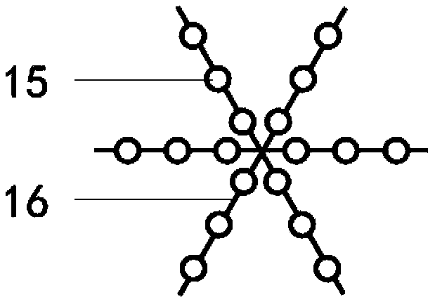
The invention belongs to the technical field of biomass energy sources and particularly discloses a biomass pyrolysis gasification system and application thereof. The system comprises a feeding device, a pyrolysis chamber and a gasification chamber, wherein the feeding device is connected with the pyrolysis chamber and used for feeding biomass raw materials into the pyrolysis chamber; the top of the pyrolysis chamber is connected with a pyrolysis gas conveying pipe for conveying pyrolysis gas outwards, and the bottom of the pyrolysis chamber is provided with a pyrolysis coke outlet for conveying pyrolysis coke into the gasification chamber. The gasification chamber sleeves the pyrolysis chamber to form a sleeve structure, the top of the gasification chamber is connected with a gasifying gas conveying pipe for conveying gasifying gas outwards, the gasifying gas conveying pipe sleeves the feeding device to utilize the gasifying gas to bake and preheat the biomass raw materials, and baking gas generated by baking and preheating is conveyed into the gasification chamber; the bottom of the gasification chamber is provided with a gasified ash outlet which is used for conveying gasified ash generated by gasification into an ash collector. The system can be deeply coupled with a coal-fired boiler and has the advantages that the gasification efficiency is high, the comprehensive heat value of fuel gas is high, and pyrolysis gas can be used as reburning fuel.

Description

technical field [0001] The invention belongs to the technical field of biomass energy, and more specifically relates to a biomass pyrolysis gasification system and its application. Background technique [0002] With the rapid development of my country's economy, the demand for electricity has increased significantly. Coal-fired power generation is the main source of electricity production in my country. While consuming a large amount of coal resources, the pollutants it emits also have a serious impact on the environment. How to partially replace coal with other renewable energy sources on the premise of ensuring a stable supply of electricity is an important problem to be solved in today's green development environment. As the only renewable carbon source, biomass energy is second only to coal, oil and natural gas in the world's total energy consumption, and its utilization and conversion methods are well compatible with fossil energy. my country is rich in biomass resourc...

Claims


Application Information

Patent Timeline
Patent Type & Authority Patents(China)
IPC IPC(8): C10J3/60C10J3/72
CPCC10J3/60C10J3/72C10J2300/0906C10J2300/0909C10J2300/0916
Inventor 陈汉平毛俏婷谢迎谱王贤华杨海平胡俊豪曾阔邵敬爱杨晴陈应泉张世红
Owner HUAZHONG UNIV OF SCI & TECH
Learn More