Automatic measuring device and method for SO3 in flue gas

An automatic measurement and flue gas technology, which is applied in the field of pollutant testing, can solve the problems of easy measurement errors, weak degree of automation, and low measurement accuracy, and achieve the effects of convenient operation, reduced measurement impact, and improved measurement accuracy

Pending Publication Date: 2019-04-16
CHINA HUADIAN ENG
View PDF6 Cites 7 Cited by
  • Summary
  • Abstract
  • Description
  • Claims
  • Application Information

AI Technical Summary

Problems solved by technology

[0003] SO 3 The detection technology has always been difficult, first SO 3 The chemical property is lively, and it is easy to react with other substances; in the flue gas, SO 3 Concentration relative to SO 2 The concentration is small, while SO 2 to SO 3 The measurement has a great influence, so the measurement is prone to error; SO 3 Combined with water vapor in the flue gas to produce sulfuric acid, sulfuric acid will form an azeotrope with water when the temperature is below 500 °C; when the temperature drops, sulfuric acid is easy to condense, and the condensed sulfuric acid will react with the flue and the measuring pipeline, causing Measurements are low
So that in the prior art, SO 3 The measurement accuracy is low, the reliability is poor, and the degree of automation is not strong

Method used


Image

  • Automatic measuring device and method for SO3 in flue gas
  • Automatic measuring device and method for SO3 in flue gas
  • Automatic measuring device and method for SO3 in flue gas

Examples


Embodiment 1

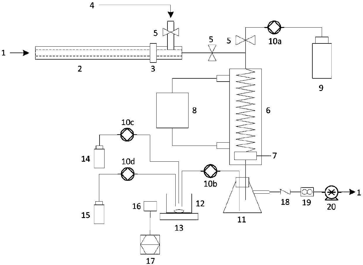
[0035] Embodiment 1 of the present invention: as figure 1 and figure 2 As shown, SO in a flue gas 3 The automatic measuring device includes a sampling system, a collection system, an analysis system and a control system. The flue gas 1 enters the sampling system, and the sampling system, the collection system, and the analysis system are connected in sequence through pipelines. The sampling system, the collection system, and the analysis system are all The signal is connected to the control system; wherein the sampling system includes a sampling gun 2, a filter 3 and a compressed air system 4, a filter 3 is installed at one end of the sampling gun 2, and a pipe is connected above the end of the sampling gun 2 Compressed air system 4; The sampling system also includes a check valve 18, a flow meter 19, and an air pump 20 connected in sequence through the pipeline, and the end of the check valve 18 away from the flow meter 19 is connected to the sample collection bottle 11 thr...

Embodiment 2

[0037] Embodiment 2: as figure 1 and figure 2 As shown, SO in a flue gas 3 The automatic measuring device includes a sampling system, a collection system, an analysis system and a control system. The flue gas 1 enters the sampling system, and the sampling system, the collection system, and the analysis system are connected in sequence through pipelines. The sampling system, the collection system, and the analysis system are all The signal is connected to the control system; wherein the sampling system includes a sampling gun 2, a filter 3 and a compressed air system 4, a filter 3 is installed at one end of the sampling gun 2, and a pipe is connected above the end of the sampling gun 2 Compressed air system 4; The sampling system also includes a check valve 18, a flow meter 19, and an air pump 20 connected in sequence through the pipeline, and the end of the check valve 18 away from the flow meter 19 is connected to the sample collection bottle 11 through a pipeline; The sys...

Embodiment 3

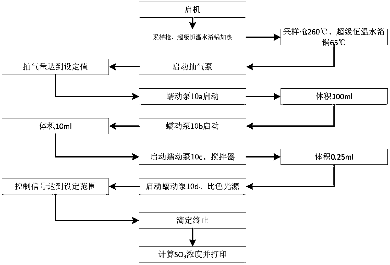
[0040] Embodiment 3: as figure 1 and figure 2 As shown, SO in a flue gas 3 Automatic measurement method, using the aforementioned SO in flue gas 3 Automatic measuring devices, including the following processes:

[0041] After the device is started, the sampling gun 2 and the super constant temperature water bath 8 start heating, and after reaching the design temperature, start the air pump 20;

[0042] The sampling gun 2 heats the extracted flue gas 1 to raise the temperature. After the flue gas passes through the filter 3 to remove dust, it enters the condenser 6. Under the action of the condenser 6 and the sintered glass filter 7, the SO in the flue gas 3 captured;

[0043] Start the peristaltic pump a10a on the pipeline connecting the eluent container 9 and the condenser 6, extract 100 ml of eluent from the eluent container 9 to flush the condenser 6 and the sintered glass filter 7, and then enter the sample collection bottle 11 to be trapped SO 3 The exhausted flue ...


PUM


Abstract

The invention relates to the field of pollutant testing, and in particular relates to an automatic measuring device and method for SO3 in flue gas. The device provided by the invention comprises a sampling system, a collecting system, an analysis system and a control system. Flue gas enters the sampling system. The sampling system, the collecting system and the analysis system are sequentially connected through a pipeline. The sampling system, the collecting system and the analysis system are in signal connection with the control system. The sampling system comprises a sampling gun, a filter and a compressed air system. The filter is arranged on one end of the sampling gun. The compressed air system is connected with the upper part of the end of the sampling gun through a pipeline. According to the invention, SO3 in flue gas is collected based on a controlled condensation method; acid radical ion measurement is carried out based on acid-base titration; the SO3 concentration in flue gasis calculated in combination with the flue gas sampling volume, which can reduce the influence of flue gas dust on SO3 measurement and improve the measurement accuracy and reliability; and the deviceand method have the advantages of high automation and convenient operation, and are suitable for automatic measurement of SO3 in flue gas.

Description

technical field [0001] The invention relates to the field of pollutant testing, in particular to a method for measuring SO in flue gas 3 Automatic measuring device and method. Background technique [0002] SO 3 It is an important pollutant in coal-fired power plants, and its hazards are: (1) increase the acid dew point, accelerate equipment corrosion, and pose a threat to the safety and economy of coal-fired power plants; (2) increase the opacity of exhaust smoke or produce blue smoke, which is easy to cause The masses are worried about the pollution situation; (3) the important precursor substances formed by fine particles, aggravating air pollution; (4) stimulating the ear, nose, throat and respiratory system, endangering health; (5) competing with mercury for the adsorption site of activated carbon, affecting the smoke Air mercury removal effect. In view of the above reasons, the development of coal-fired power plant SO 3 Governance is very important, the key lies in ...

Claims


Application Information

Patent Timeline
Patent Type & Authority Applications(China)
IPC IPC(8): G01N1/24G01N21/79G01N31/16
CPCG01N1/2258G01N1/24G01N21/79G01N31/16G01N2001/2282
Inventor 于伟静马超应炬锋徐立伟
Owner CHINA HUADIAN ENG
Why Eureka
Try Eureka