
A design parameter determination method for a dual-motor drive high-frequency vibration ball mill

A high-frequency vibration and dual-machine drive technology, which is applied in computer-aided design, calculation, electrical digital data processing, etc., can solve the problems of high technical requirements of the exciter, high cost, and difficulty in accurately controlling the force and size of materials.

Active Publication Date: 2019-04-16
NORTHEASTERN UNIV
View PDF2 Cites 0 Cited by
  • Summary
  • Abstract
  • Description
  • Claims
  • Application Information

AI Technical Summary

Problems solved by technology

[0003] 1. Driven by a single exciter, the power requirement for the exciter is large, resulting in a large volume of the exciter itself, high technical requirements for the exciter, and a substantial increase in cost
[0004] 2. Although the grinding machine driven by a single machine increases the single processing capacity and improves the production efficiency, the application of a single large vibration exciter also reduces the utilization rate of electric energy
Does not meet the national energy conservation and emission reduction requirements
[0005] 3. In the process of processing, it is difficult to accurately control the size of the material strength

Method used


Image

  • A design parameter determination method for a dual-motor drive high-frequency vibration ball mill
  • A design parameter determination method for a dual-motor drive high-frequency vibration ball mill
  • A design parameter determination method for a dual-motor drive high-frequency vibration ball mill

Examples


Embodiment 1

[0177] In order to further analyze the characteristics of the system, the dual-machine drive system is taken as the research object, and its numerical analysis is carried out.

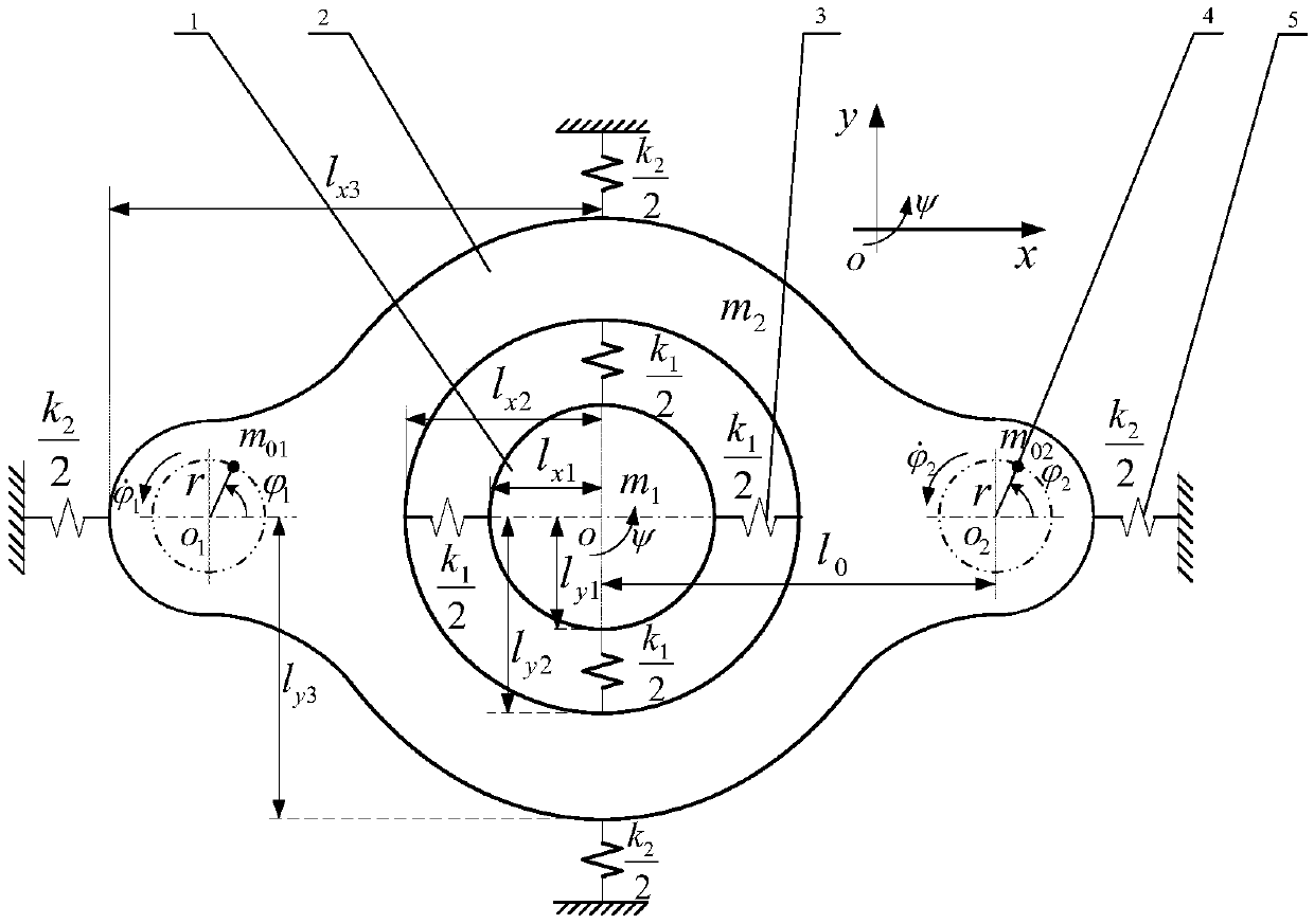
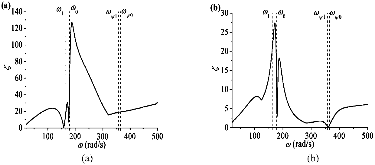
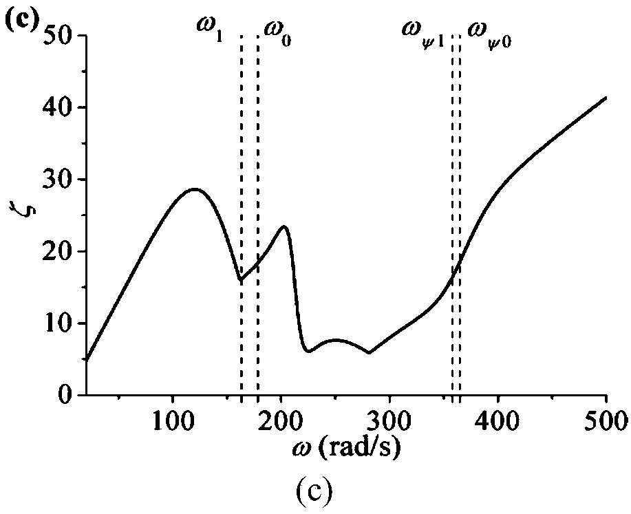
[0178] Parameters of the assumed vibration system: k 1 =8000kN / m,k ψ1 =6400kN / rad,k 2 =100kN / m,k ψ2 =88kN / rad,m 1 =300kG,m 2 =1500kG,J m1 =50kg·m 2 ,J m2 =1114.83kg·m 2 ,m 0 = 20kG, r = 0.15m, η = 1, ξ 1 =0.02,ξ 2 =0.07, ξ ψ1 =0.02, ξ ψ2 =0.07 and thus two natural frequencies ω 0 ≈178.5rad / s, ω 1 ≈163.3rad / s, ω ψ0 ≈365rad / s, ω 1 ≈357.8rad / s. Motor type: three-phase squirrel cage, 50Hz, 380V, 6-pole, 0.75kW, rated speed 980r / min. Motor parameters: rotor resistance R r =3.40Ω, stator resistance R s =3.35Ω, mutual inductance L m =164mH, rotor inductance L r =170mH, stator inductance L s =170mH,f d1 = f d2 = 0.05.

[0179] The coefficient ζ of the synchronization ability of the two rotors from the coupled dynamics is an index that can be used to describe the ability to adjust the ...

Embodiment 2

[0184]In order to further analyze and verify the numerical results, three sets of simulation results are given by the Runge-Kutta method. Vibration system parameters and motor parameters have been given in the previous section. In this section, in order to obtain the motion state of the system in different regions, generally by changing the spring stiffness k 1 and k ψ1 to adjust the value of the natural frequency.

[0185] Such as Figure 5 As shown, the spring stiffness k at this time 1 =5000kN / m,k ψ1 = 4000kN / rad to get 4 natural frequencies: ω 1 =129.1rad / s, ω 0 =141.1rad / s, ω ψ =282.8rad / s, ω ψ0 = 288.7 rad / s. Depend on Figure 5 (a) It can be seen that the synchronous speed of the motor is about 832.9r / min, that is, ω≈87.2rad / s, and there is z 0 = 0.62. At the same time, a π / 3 disturbance is given to motor 2 at 15s.

[0186] From Figure 5 (b) It can be seen that before interference, the phase difference is 2α=0°, corresponding to Figure 4 l of (b) 1 (ω=...

Embodiment 3

[0191] Below are example data parameters for one of the vibratory ball mills utilizing the present invention. The invention is not limited to this design parameter.

[0192] The parameters of the assumed vibration system: the spring stiffness k between the mass bodies 1 and 2 1 =3000kN / m, spring stiffness k between mass body 2 and foundation 2 =100kN / m, plastid 1 mass m 1 =300kG, plastid 2 mass m 2 =1500kG, mass of eccentric mass of exciter m 0 =20kG, the radius of gyration of the exciter r=0.15m, the motor speed 977.6r / min, at this time z ψ0 = 0.85. The system works in the region II. Due to the influence of the disturbance, the swing angles of the two rigid frames change very little, and the phases of the masses swinging in the ψ direction are the same, but their values ​​are very small and can be ignored. Furthermore, the displacements of the plastids are all zero in the steady state. In this case, the vibration system can be considered to be in a steady state. (Moto...


PUM


Abstract

The invention belongs to the technical field of vibration ball milling devices, and discloses a design parameter determination method for a double-machine-driven high-frequency vibration ball mill, and the vibration ball mill comprises two vibration exciters, a mass 1, a mass 2, a spring A and a spring B; Wherein the plastid 1 and the plastid 2 are both of a central symmetry structure and an axialsymmetry structure, and the plastid 1 is located in the central space of the plastid 2 and connected with the inner wall of the plastid 2 through the spring A; The symmetrical edges of the plastid 2are connected with a foundation through springs B; Wherein the two vibration exciters are symmetrically arranged in the mass 2, an eccentric rotor is arranged in each of the two vibration exciters, the eccentric rotors are driven by respective induction motors to rotate around the centers of rotation axes respectively, the rotation directions are anticlockwise, the rotation speeds are the same, and the self-synchronizing vibration drives the ball mill to work. Relative motion of the plastid is discussed by establishing a kinetic model and a motion differential equation, and a synchronism condition and a stability condition are derived. And the crushing efficiency and the energy utilization rate of the vibrating ball mill are improved.

Description

field of invention [0001] The invention belongs to the technical field of vibrating ball milling devices, and relates to a method for determining design parameters of a double-machine-driven high-frequency vibrating ball mill. Background technique [0002] Vibrating ball mill is a kind of chemical machinery, which can grind the material to the micron level by forming a strong impact crushing and grinding effect on the material. Widely used in ceramics, non-metallic minerals, pigments, electronics, chemicals, metallurgy, building materials, new materials, food and pharmaceuticals and other fields. It is used for fine crushing, its efficiency is twice as high as that of ordinary ball mills, and it has the advantages of simple structure and low cost. The invention belongs to a large vibration ball mill among vibration ball mills. Ordinary large-scale vibratory grinders have the same principle as small-scale vibratory grinders, and they are driven by a single machine, and the ...

Claims


Application Information

Patent Timeline
IPC IPC(8): G06F17/50
CPCG06F30/17G06F2119/06Y02T90/00
Inventor 张学良王志辉徐金林高志国岳红亮马辉闻邦椿
Owner NORTHEASTERN UNIV
Learn More