Shearing method

A processing method and a technology of processed parts, which are applied in the direction of shearing devices, metal processing equipment, manufacturing tools, etc., can solve the problems of undisclosed shearing processing, easy fracture of welding parts, and damage of punches, etc., and achieve fatigue resistance And the effect of excellent hydrogen embrittlement resistance, excellent surface properties, and long life

Active Publication Date: 2021-06-11
NIPPON STEEL CORP
View PDF11 Cites 0 Cited by
  • Summary
  • Abstract
  • Description
  • Claims
  • Application Information

AI Technical Summary

Problems solved by technology

However, the sheared surface formed by the method of Patent Document 1 has difficulties
That is, when the shape of the punch is made uniform in the direction of the cutting ridge line, there is a problem that fractures are likely to occur in the welded part with low ductility and toughness in the above-mentioned sheared surface.
[0012] When the shear processing conditions are controlled in such a way that the residual stress of the welded part is preferentially reduced, the fatigue resistance and hydrogen embrittlement resistance can be further improved in the shear processed surface of the workpiece, but when as shown in the non-patent literature 1, when the thickness ratio between the gap between the punch and the die and the thickness of the workpiece is 1% or less, due to the slight offset of the punch, there is contact between the punch and the die, and the punch and / or or the risk of die breakage
[0013] In addition, when the thickness ratio between the gap between the punch and the die and the thickness of the workpiece is 1% or less, the side of the punch and / or the die is worn and the gap changes, and in the sheared surface of the workpiece, there is The problem that the effect of improving fatigue resistance and hydrogen embrittlement resistance cannot be sufficiently obtained
[0014] In addition, the punching method of Patent Document 2, the press forming method of Patent Document 3, and the trimming device of Patent Document 4 do not disclose shearing in which shearing is performed along a shearing line intersecting a welded part.
That is, none of Patent Documents 1 to 3 discloses the conditions for reducing the residual stress on the sheared surface of the welded portion.

Method used


Image

  • Shearing method
  • Shearing method
  • Shearing method

Examples


Embodiment

[0159] Next, examples of the present invention will be described. The conditions in the examples are examples of conditions employed to confirm the feasibility and effects of the present invention, and the present invention is not limited to the examples of conditions. The present invention can adopt various conditions as long as the object of the present invention is achieved without departing from the gist of the present invention.

[0160] (Example)

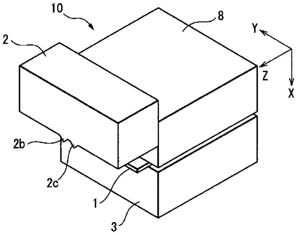
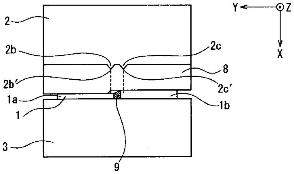
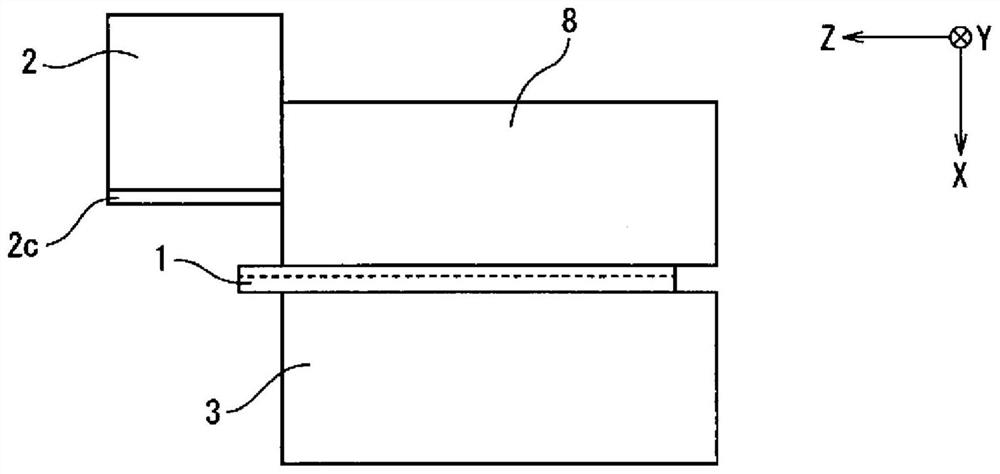
[0161] A 780MPa-grade steel plate with a thickness of 1.4mm is welded to a 1180MPa-grade steel plate with a thickness of 1.6mm to manufacture workpieces (step width Δt=0.2mm, hereinafter referred to as "78-118 pieces"), by Figure 1~3 The shearing device shown (with 2 protrusions at the tip of the punch) sheared pieces 78-118.

[0162] The shape of the protrusion was H = 1 mm, width Wb (Wc) = 2 mm at the base end, and angle α = 90°. The width d of the welded portion is 2 mm, so the distance D between the front ends of the pr...


PUM

PropertyMeasurementUnit
strengthaaaaaaaaaa
thicknessaaaaaaaaaa

Abstract

The present invention provides a shearing processing method. For a workpiece obtained by welding a steel plate with a large step width at the welded portion and / or with a strength of 1000 MPa or more and other steel plates, the shearing line crossing the welded portion is In the shearing process in which the shearing process is performed, a sheared surface with less residual stress and excellent surface properties is formed, and the life of the punch is prolonged. The shearing method of the present invention is to use a punch and a die to shear a workpiece having a welded portion, wherein two protrusions are provided on the tip of the punch, and the two protrusions are clamped from both sides. Hold all or part of the welded part of the workpiece, and shear the workpiece along the cutting line intersecting the welded part.

Description

technical field [0001] The present invention relates to iron, copper, zinc, tin, aluminum, titanium, magnesium, or alloys based on these used in automobiles, home appliances, building structures, ships, bridges, construction machinery, various factories, etc. A method of shearing a metal plate, and particularly relates to a method of shearing capable of improving fatigue properties and hydrogen embrittlement resistance in a sheared surface of welded metal plates. Background technique [0002] Shearing processes such as blanking and punching of metal sheets based on stamping are widely used in the processing of electronic equipment and automotive parts due to their high productivity and low processing costs. However, when a high-strength steel sheet exceeding 1000 MPa is subjected to shear processing, the tensile residual stress (hereinafter, unless specifically denied, the tensile residual stress is simply described as "residual residual stress) in the punched end surface (s...

Claims


Application Information

Patent Timeline
Patent Type & Authority Patents(China)
IPC IPC(8): B23D15/04B21D28/00B21D28/34B23D15/06
CPCB21D28/00B23D15/04B23D15/06B21D28/34B23D35/001
Inventor 安富隆齐藤雅宽米村繁吉田亨
Owner NIPPON STEEL CORP
Why Eureka
Try Eureka