
Laser shock punching device based on rotating electromagnetic field and water-based ultrasonic vibrating

A technology of ultrasonic vibration and laser shock, used in laser welding equipment, welding equipment, metal processing equipment, etc., can solve the problem of affecting the quality of laser drilling and the stability of the laser drilling process, affecting the heat input distribution and efficiency of the laser heat source. To research and application reports and other issues, to improve the punching quality, avoid adverse effects and influences, and reduce the effect of shielding effects

Active Publication Date: 2019-04-19
JIANGSU UNIV
View PDF6 Cites 13 Cited by
  • Summary
  • Abstract
  • Description
  • Claims
  • Application Information

AI Technical Summary

Problems solved by technology

The greater the density of the photoinduced plasma, the more obvious the shielding, scattering and refraction of the incident laser radiation energy, which affects the heat input distribution and efficiency of the laser heat source, resulting in a decrease in the efficiency of the laser impact drilling, and the movement of the plasma It will also affect the quality of laser drilling and the stability of the laser drilling process
In addition, laser shock drilling is usually a thermal process, and the solidification of laser-processed surface residues not only changes the metallurgical state, but also causes problems such as the formation of recast layers, microcracks, spatter, and residual stress
However, there are no domestic and foreign research and application reports on the simultaneous coupling of water-based ultrasonic vibration, electric field and magnetic field to assist laser processing.

Method used


Image

  • Laser shock punching device based on rotating electromagnetic field and water-based ultrasonic vibrating
  • Laser shock punching device based on rotating electromagnetic field and water-based ultrasonic vibrating
  • Laser shock punching device based on rotating electromagnetic field and water-based ultrasonic vibrating

Examples


Embodiment Construction

[0031] The embodiments of the present invention are described in detail below. Examples of the embodiments are shown in the accompanying drawings, in which the same or similar reference numerals indicate the same or similar elements or elements with the same or similar functions. The embodiments described below with reference to the accompanying drawings are exemplary, and are intended to explain the present invention, but should not be construed as limiting the present invention.

[0032] In the description of the present invention, it should be understood that the terms "center", "longitudinal", "transverse", "length", "width", "thickness", "upper", "lower", "axial", The orientation or positional relationship indicated by "radial", "vertical", "horizontal", "inner", "outer", etc. are based on the orientation or positional relationship shown in the drawings, and are only for the convenience of describing the present invention and simplifying the description , Rather than indicat...


PUM


Abstract

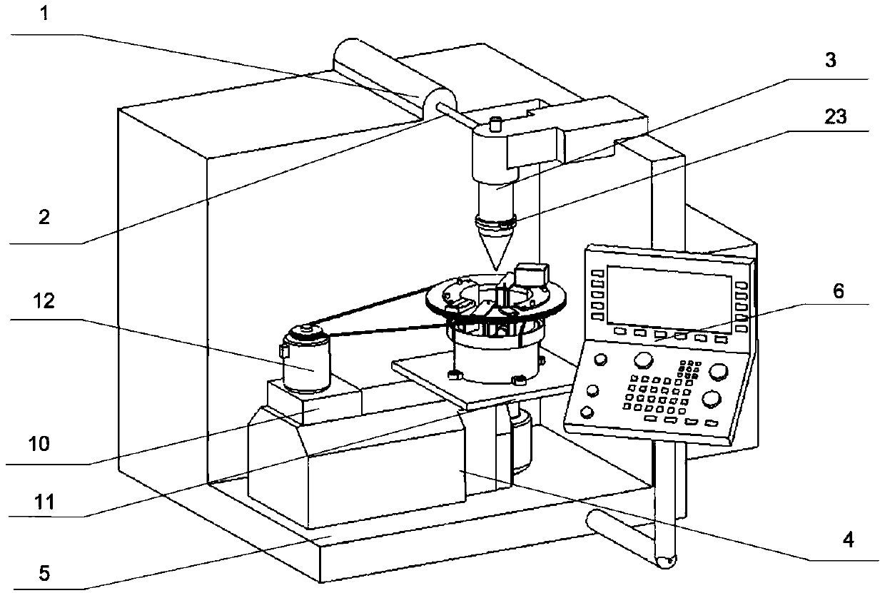
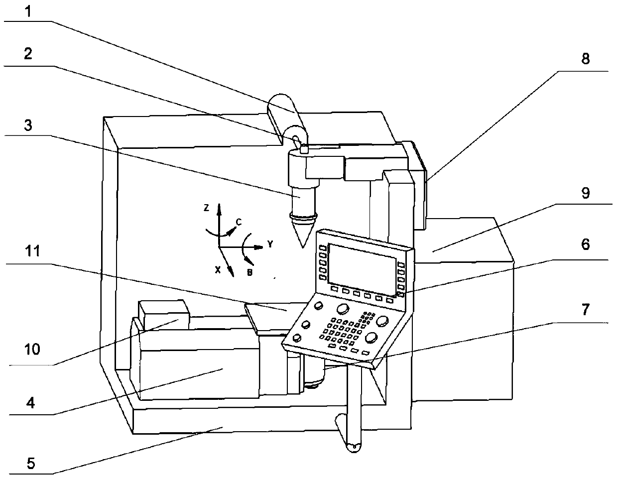
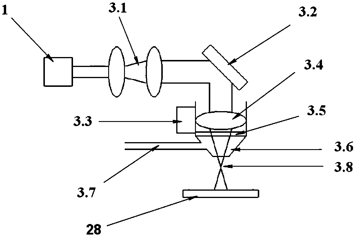
The invention provides a laser shock punching device based on a rotating electromagnetic field and a water-based ultrasonic vibrating. The device comprises a laser machining center, an ultrasonic auxiliary unit, an electromagnetic auxiliary unit and a workpiece clamping unit, wherein the electromagnetic auxiliary unit comprises a driving mechanism, a bracket, an electric field generating device, two electrode plates, two electromagnets and an electromagnetic adjusting device, wherein the bracket is a rotary body, the driving mechanism is used for driving the bracket to rotate around the axis of the bracket, the two electrode plates and the two electromagnets are uniformly distributed on the inner surface of the bracket in the circumferential direction by taking the axis of the bracket as the center, and the electrode plates and the electromagnets are arranged at intervals. According to the device, the shielding, scattering and refraction effects of the plasma can be weakened, the heatinput efficiency of a laser beam is improved, electromagnetic stirring can be generated in molten metal, micro cracks of the wall of the hole can be repaired, and meanwhile grains and tissues can be refined, the mechanical property is improved, the residual stress is effectively reduced, the punching efficiency is improved, the punching depth is increased, and the punching quality is improved.

Description

Technical field [0001] The invention relates to the field of laser manufacturing and processing, and in particular to a laser impact drilling device based on a rotating electromagnetic field and water-based ultrasonic vibration. Background technique [0002] Laser drilling is one of the main R&D and application directions in the field of laser processing. Compared with traditional hole making technology, laser shock drilling has the advantages of wide range of processing materials, fast hole making speed, non-contact and pollution-free processing, and high economic benefits. Therefore, pulsed lasers are widely used in precision machining of group holes of hot end parts of aero-engines. [0003] However, in the process of laser shock drilling, the higher the laser power density, the more intense the material heating and melting and vaporization, and the denser the steam and photo-induced plasma produced. The greater the density of the photo-induced plasma, the more obvious the shi...

Claims


Application Information

Patent Timeline
Patent Type & Authority Applications(China)
IPC IPC(8): B23K26/382B23K26/70
CPCB23K26/382B23K26/702
Inventor 王后孝徐烨朱苏凯单佳欣
Owner JIANGSU UNIV
Learn More