
Vertical compound heading machine

A compound type, roadheader technology, applied in construction, earth-moving drilling, drilling equipment, etc., can solve the problems of unsatisfactory assembly effect, only one absorption port, low construction efficiency, etc., to achieve simple structure and improve operation efficiency. , The effect of improving installation accuracy and efficiency

Inactive Publication Date: 2019-04-19
亨通海洋工程有限公司
View PDF0 Cites 0 Cited by
  • Summary
  • Abstract
  • Description
  • Claims
  • Application Information

AI Technical Summary

Problems solved by technology

[0003] Nowadays, in the actual use process, it is found that the performance of conventional roadheaders has the following deficiencies: ① Insufficient WOB, WOB ≤ 150T; ② Insufficient torque, torque ≤ 1000KN.m; ③ Low slag discharge efficiency, only one suction port;
After the drilling is completed, it is also necessary to remove the drill pipes one by one to lift and take out the drilling tool; therefore, the disassembly and assembly of the drill pipe is an important link with a high repetition rate in the drilling construction; the disassembly and assembly of the conventional rock-socketed drilling equipment The rods are operated by cranes and manually, which is not only inefficient, but also the assembly effect is not satisfactory; at the same time, in conventional rock-socketed drilling equipment, multi-section drill pipes are usually stacked horizontally on the deck platform When hoisting, it needs to be turned over to the vertical state before disassembly and assembly, which undoubtedly further reduces its construction efficiency; and the safety performance of the horizontal stacking method is not good, especially in severe wind and waves, the drill pipe is prone to roll, thereby affecting the progress of its construction

Method used


Image

  • Vertical compound heading machine
  • Vertical compound heading machine
  • Vertical compound heading machine

Examples


Embodiment Construction

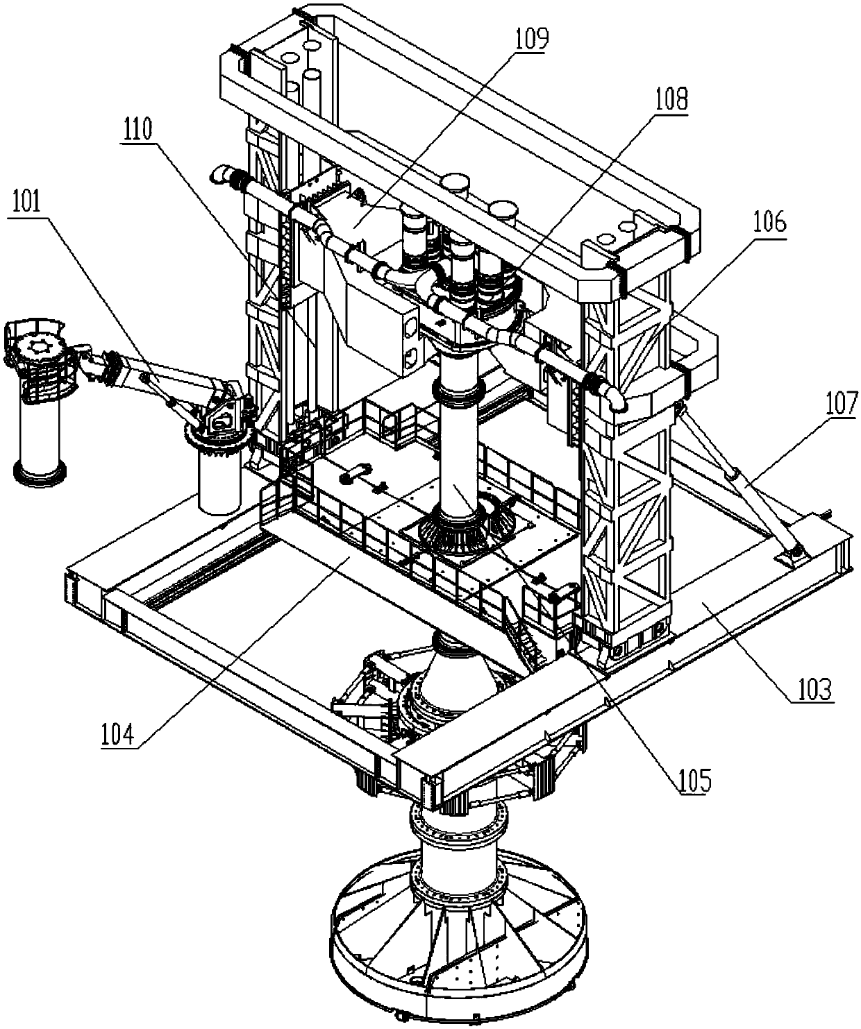
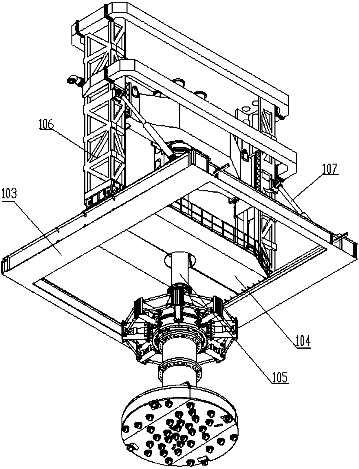
[0068] see Figure 1-25 , a kind of vertical compound roadheading machine that the present invention relates to includes a drilling rig chassis 103, a manipulator 101 is installed on the drilling rig chassis 103, two sealing platforms 104 are slidably arranged on the drilling rig chassis 103, and between the two sealing platforms 104 The drill pipe assembly 105 is clamped vertically, the gantry 106 is installed on the chassis 103 of the drilling rig, the inner side of the vertical bar of the gantry 106 is vertically provided with guide rails, and the left and right ends of the horizontally arranged lifting platform 109 are respectively slid on the gantry 106 In the guide rails on both sides, the piston rod of the vertically arranged hydraulic cylinder 110 is connected to the lifting platform 109, and the power head 108 installed on the lifting platform 109 drives the drill pipe assembly 105;

[0069] The bottom of described gantry 106 is hinged with rig chassis 103 by pin shaf...


PUM


Abstract

The invention discloses a vertical compound heading machine which comprises a drilling machine base (103), a manipulator (101), two sealing platforms (104) and a portal frame (106). The manipulator (101) is mounted on the drilling machine base (103), the two sealing platforms (104) are slidably arranged on the drilling machine base (103), a drilling rod component (105) is vertically clamped between the two sealing platforms (104), the portal frame (106) is mounted on the drilling machine base (103), guide rails are vertically arranged on the inner sides of vertical rods of the portal frame (106), the left end and the right end of a horizontal lifting table (109) slide in the guide rails of two sides of the portal frame (106), a piston rod of a vertical hydraulic cylinder (110) is connectedwith the lifting table (109), and a power head (108) mounted on the lifting table (109) drives the drilling rod component (105). The vertical compound heading machine is high in construction efficiency and good in construction effect.

Description

technical field [0001] The invention relates to a vertical compound roadheader, in particular to a vertical compound roadheader used in offshore wind power construction. Background technique [0002] At present, in the construction of offshore wind power, the large-diameter single-pile rock-socketed drilling method carried out by the vertical compound roadheader has been widely used; for the vertical compound type roadheader, the factors that determine its performance are: ① Applied ② The torque provided to the drill bit ③ The speed of the drilling tool ④ The maximum lifting capacity ⑤ The efficiency of removing drilling slag from the working face; [0003] Nowadays, in the actual use process, it is found that the performance of conventional roadheaders has the following deficiencies: ① Insufficient WOB, WOB ≤ 150T; ② Insufficient torque, torque ≤ 1000KN.m; ③ Low slag discharge efficiency, only one suction port; [0004] And in actual use, it is found that the conventional ...

Claims


Application Information

Patent Timeline
IPC IPC(8): E21B7/12E21B19/18E21B10/43E21B10/60E21B17/04E21B17/18E21B21/14E21B15/02
CPCE21B7/12E21B10/43E21B10/602E21B15/02E21B17/04E21B17/18E21B19/18E21B21/14
Inventor 丁明丁志宏钱骏王瑜徐谦
Owner 亨通海洋工程有限公司
Learn More