Coal liquefaction system with forced circulation hot wall reactor and bubbling bed cold wall reactor

A technology of forced circulation and reaction system, applied in chemical instruments and methods, chemical/physical processes, preparation of liquid hydrocarbon mixtures, etc., can solve problems that have not been reported

Active Publication Date: 2019-05-07
洛阳瑞华新能源技术发展有限公司
View PDF4 Cites 1 Cited by
  • Summary
  • Abstract
  • Description
  • Claims
  • Application Information

AI Technical Summary

Problems solved by technology

[0011] Similar technical scheme of

Method used


Image

  • Coal liquefaction system with forced circulation hot wall reactor and bubbling bed cold wall reactor
  • Coal liquefaction system with forced circulation hot wall reactor and bubbling bed cold wall reactor
  • Coal liquefaction system with forced circulation hot wall reactor and bubbling bed cold wall reactor

Examples


Embodiment 1

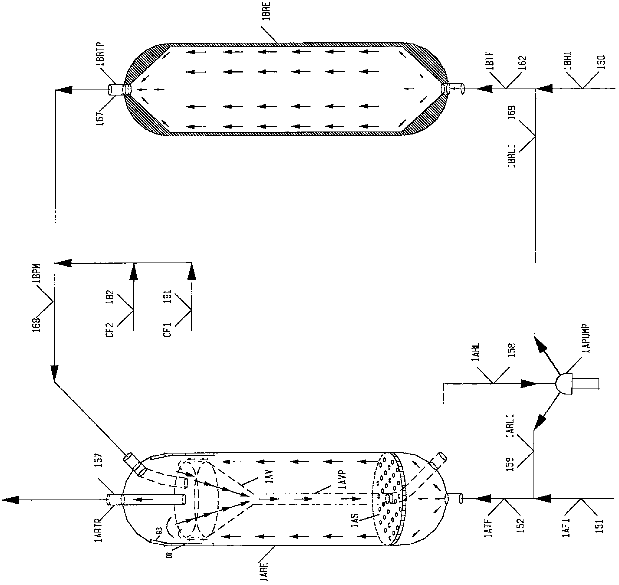
[0495] In the process of this example, the coal hydrogenation direct liquefaction reaction process RU, the first reactor AUE01 for processing coal slurry is a suspended bed coal with a diameter of 4.86 meters and a barrel section length of 35 meters. The flow structure and operating conditions of the hydrogenation direct liquefaction reactor are exactly the same as those of the comparative example.

[0496] The upper space of the first reactor AUE01 is arranged with a built-in gas-liquid-liquid separation part, that is, a liquid collection cup. Part of the liquid phase product enters the liquid collection cup, flows out of the bottom of the reactor along the catheter, and passes through the liquid material circulation pump of the first reactor. After PUMP01 is pressurized, the first path returns to the first reactor AUE01, and the second path enters the bottom of the second reactor AUE02A as a primary hydrogenation liquid product; other miscible gas-liquid products of the first...

Embodiment 2

[0510] Based on Example 1, in order to give full play to the advantages of the third reactor AUE02B, which is a liquid-material circulating cold-wall suspended bed empty cylinder reactor, with high hydrogen partial pressure and great potential for increasing the reaction temperature, the reaction temperature is adjusted to 470-480°C, which further increases the thermal cracking reaction rate of coal slurry, and can increase the coal liquefaction rate again by 1.0-1.5% (for the raw coal of the device).

[0511] Table 7 is a summary table of operating conditions of the second-stage coal hydrogenation direct liquefaction reactor in Example 2.

[0512] The product of the third reactor AUE02B is mixed with the cooling stream (quenched hydrogen or quenched oil) to cool down to 465-470°C, and then enters the gas-liquid separation space at the top of the second reactor AUE02A.

[0513] In order to prolong the continuous operation period of the device, or in order to increase the opera...

Embodiment 3

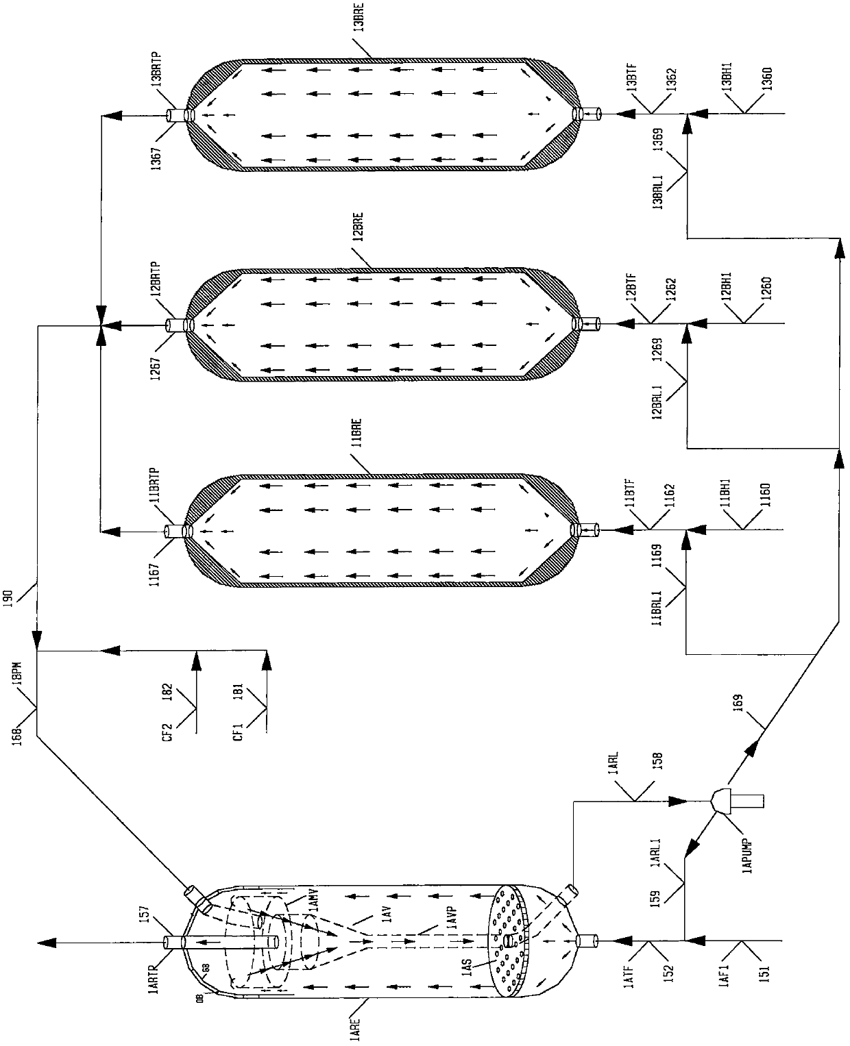
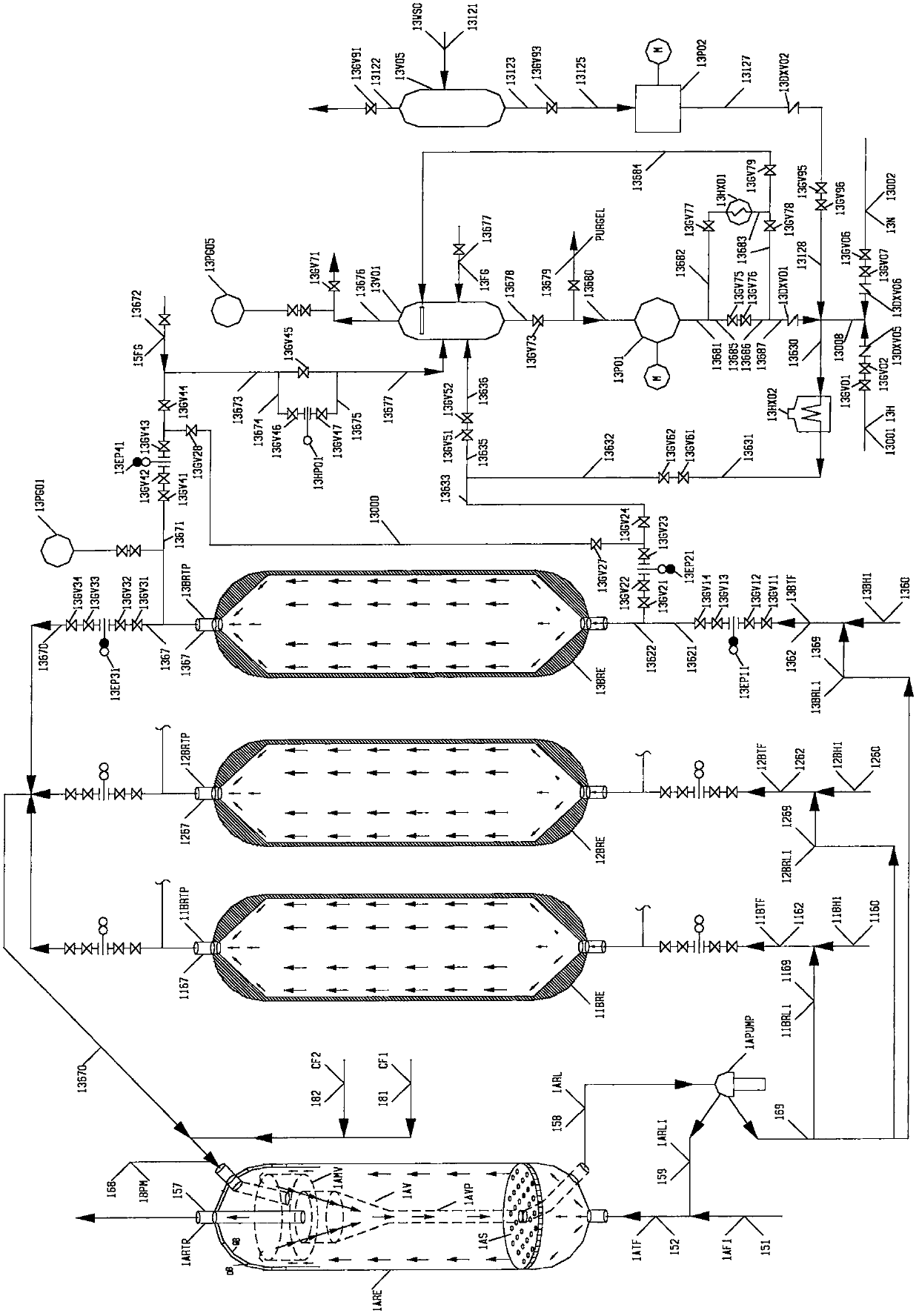
[0521] Based on Example 1, in order to fully increase the partial pressure of hydrogen in the reaction space and reduce the total operating pressure of the device, the first reactor AUE01 with a diameter of 4.86 meters and a cylinder section length of 35 meters was used with two series-operated diameters of 4.86 meters. The liquid product forced circulation reactor AUE01A and the liquid product forced circulation reactor AUE01B with a cylinder section length of 20 meters are replaced, that is, under the condition that the reaction residence time remains unchanged, a set of liquid collection cups, collection A reaction stage is added to the liquid outlet pipe system and the circulating pump system, so that the overall reaction system is as attached Figure 9 The process shown is a three-stage coal hydrogenation direct liquefaction reaction system, and the third stage belongs to a parallel coupling reaction system composed of two typical suspension bed hydrogenation reactors for ...


PUM


Abstract

The invention discloses a coal liquefaction system with a forced circulation hot wall reactor and a bubbling bed cold wall reactor. In a coal hydrogenation direct liquefaction reaction process, the forced circulation hot wall reactor is adopted in a shallow coal liquefaction reaction process with a low operation temperature, so that advantages of the existing hot wall reactor manufacturing technology is adopted to realize equipment enlargement and improve the space liquid phase fraction of the reaction; and the bubbling bed cold wall reactor is adopted in a deep coal liquefaction reaction process with a relatively high operation temperature, so that the reaction temperature of a deep thermal cracking process is reasonably improved, and the liquefaction rate of coal can be improved. When the product of the rear bubbling bed cold wall reactor returns to the adjacent upstream forced circulation hot wall reactor and a coupled parallel reaction system is formed, an ideal bubbling bed cold wall reactor with liquid material cyclic high-temperature operation is formed, so that the temperature increase amplitude, of the subsequent flow, caused by overtemperature of the product of the bubbling bed cold wall reactor can be favorably inhibited; a circulating pump can be shared, and two or more of the parallel bubbling bed cold wall reactors can form a non-stop on-line switching operation mode, so that the operation period can be prolonged.

Description

technical field [0001] The invention relates to a coal liquefaction system using a forced circulation hot wall reactor and a bubbling bed cold wall reactor. In the direct liquefaction reaction process of coal hydrogenation, the forced circulation hot wall reactor is used in the shallow coal liquefaction reaction process with a lower operating temperature To make full use of the advantages of the existing hot wall reactor manufacturing technology to realize large-scale equipment, increase the liquid phase fraction of the reaction space, and use bubbling bed cold wall reactors in the deep coal liquefaction reaction process with high operating temperature to reasonably increase the depth of thermal cracking Process reaction temperature, increase coal liquefaction rate; when the product of the rear bubbling bed cold wall reactor is returned to the adjacent upstream forced circulation hot wall reactor to form a coupled parallel reaction system, an ideal liquid material circulation h...

Claims


Application Information

Patent Timeline
IPC IPC(8): C10G1/06C10G1/08B01J8/22B01J8/18
Inventor 何巨堂
Owner 洛阳瑞华新能源技术发展有限公司
Why Eureka
Try Eureka