
A push system for a self-expanding stent

A self-expanding, push-rod technology, applied in the field of interventional therapy devices and medical devices, can solve problems such as low compliance, inability to pass stent conveyors, waste of medical resources, etc., to increase safety and accuracy, shorten operation time, simple structure

Inactive Publication Date: 2020-08-07
NANHUA UNIV
View PDF5 Cites 0 Cited by
  • Summary
  • Abstract
  • Description
  • Claims
  • Application Information

AI Technical Summary

Problems solved by technology

This has not only caused a waste of medical resources, but also increased the economic burden on patients
[0008] 2. Peripheral blood vessels and digestive tract usually have many physiological bends. When the existing stent delivery system performs stent implantation on patients with digestive tract or vascular stenosis, it is easy to cause the stent delivery device to fail to pass through the lumen with a large bending angle.
At the same time, the low-compliance stent delivery system will cause greater damage to the luminal endothelium
[0009] 3. Due to the peristalsis of the intestinal tract during the operation, the release of the currently used stent will cause inaccurate positioning. When the release position is not ideal, the stent cannot be withdrawn in time in the catheter.
[0010] 4. The existing stent and delivery system are single-use. If multiple stents need to be placed on the lesion, the stent delivery gun must be withdrawn and entered multiple times, which will significantly prolong the operation time and increase the damage of the lumen intima

Method used


Image

  • A push system for a self-expanding stent
  • A push system for a self-expanding stent
  • A push system for a self-expanding stent

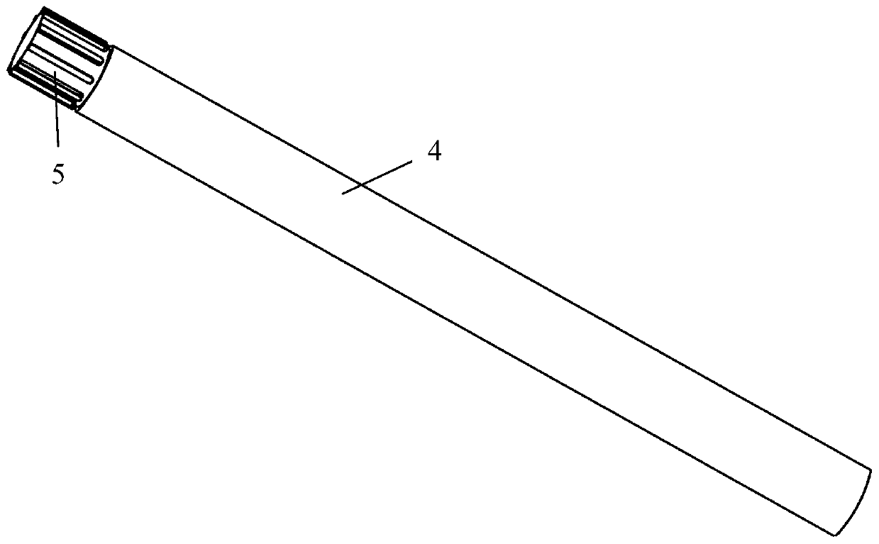
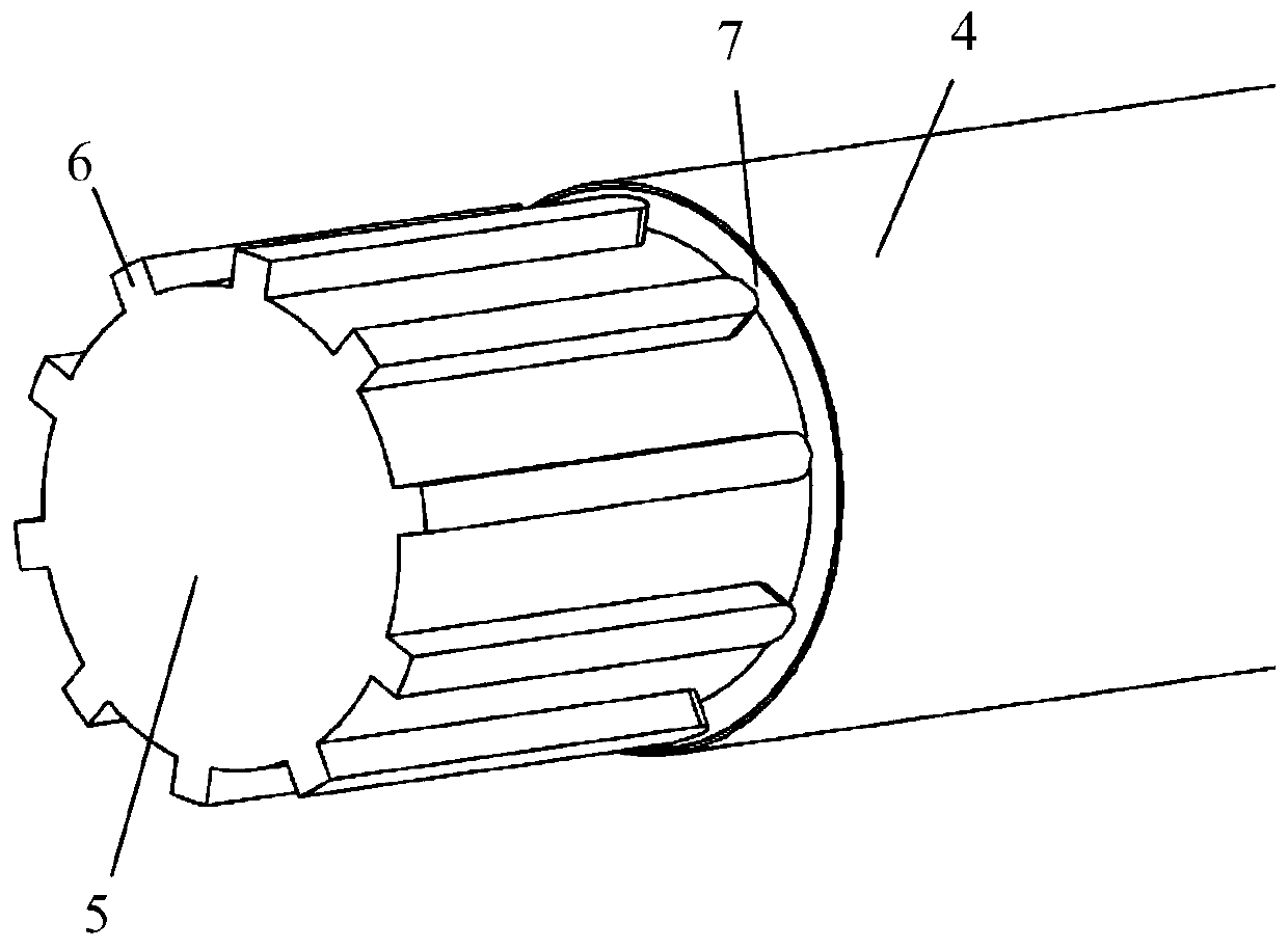
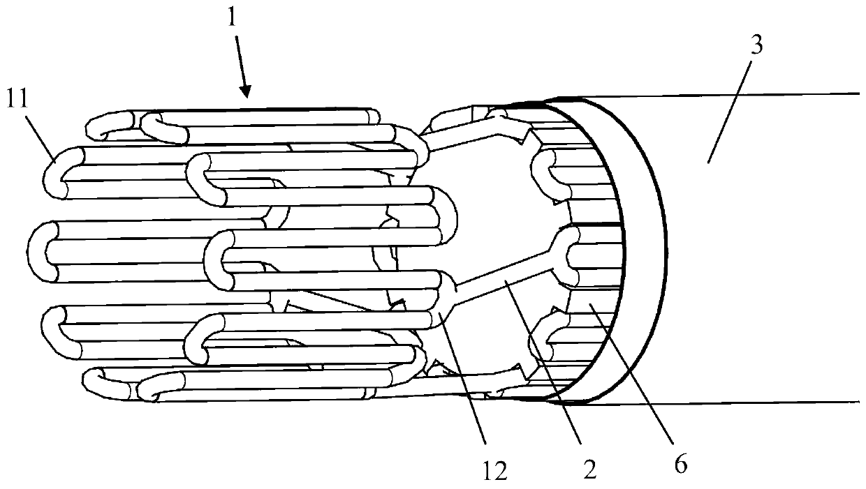
Examples


Embodiment Construction

[0027] The present invention will be described in further detail below in conjunction with the accompanying drawings.

[0028] see Figure 1-6 , a self-expanding stent, in the shape of a tube, comprising more than two annular components 1 ( Figure 5 two are shown), two adjacent annular components 1 are connected by a connecting piece 2 along the axial direction of the pipe, and the annular components 1 are wave-shaped after being deployed along the circumference. shape transition. The annular part 1 of the self-expanding stent is similar to a plurality of U-shaped parts connected by an arc part, and is evenly distributed along the circumferential direction of the tube. The self-expanding stent is in a compressed state before release, and the diameter of the tube is small. When the stent is released, the diameter expands according to its own elasticity, and each U-shaped part expands, and the tube diameter expands to expand the narrow channel in the living body. Preferably,...


PUM


Abstract

The invention discloses a self-expansion support and a pushing system thereof. The pushing system comprises a guide pipe, a push rod and the self-expansion support, and the diameter of the push rod issmaller than the inner diameter of the guide pipe; one end of the push rod is provided with a cylindrical support mounting part, the support mounting part is coaxial with the push rod, and the diameter of the support mounting part is smaller than that of the push rod; the support mounting part is provided with two or more protrusions, gaps capable of containing annular part troughs of the end ofthe self-expansion support are formed between the protrusions and the push rod, when the self-expansion support is located between the guide and the support mounting part, the self-expansion support is in a compressed state, and the protrusions and the push rod can limit the axial movement of the self-expansion support relative to the push rod. The pushing system is simple in structure, precise release of the support is conveniently achieved, compared with an existing support conveying system, the surgery safety and precision are improved, and through the laid guide pipes, multiple supports are installed and released, which helps to shorten the surgery time and reduce the injury of the blood vessel or the intestinal inner membrane.

Description

technical field [0001] The invention belongs to the field of medical equipment, in particular to the field of interventional treatment equipment, and relates to a push system for a self-expanding bracket. Background technique [0002] A stent for indwelling in a living body is usually tubular, and is placed in the stent in order to treat various diseases caused by stenosis or occlusion of a blood vessel or other lumen in a living body, to expand the stenosis or occlusion, and to secure the lumen. Medical equipment in the cavity. For self-expanding stents, the stent itself has an expansion function, and the stent is stored in the outer sheath in a thinner state and inserted into the living body, and released from the outer sheath at the target site, thereby returning to the original expanded state and tightening. The paste is fixed on the inner wall of the lumen to maintain the shape of the lumen. [0003] Metal stents are available for the following two types of obstructio...

Claims


Application Information

Patent Timeline
Patent Type & Authority Patents(China)
IPC IPC(8): A61F2/82A61F2/966
Inventor 尹凯张耀元
Owner NANHUA UNIV
Learn More