A preparation process of thermally conductive electrical insulation foam tape for high temperature

A thermal conductivity, high temperature technology, used in adhesives, polymer adhesive additives, film/sheet adhesives, etc., can solve the problems of no flame retardant, waste of resources, no heat insulation, etc., to reduce the environment The effect of pollution

Active Publication Date: 2021-06-29
苏州泰富金电子科技有限公司
View PDF4 Cites 0 Cited by
  • Summary
  • Abstract
  • Description
  • Claims
  • Application Information

AI Technical Summary

Problems solved by technology

[0004] 1. Traditional PE, PU and melamine foam have good cushioning and insulation properties, but due to the limitation of processing technology, it is impossible to obtain a high foaming ratio and ultra-thin insulating foam material layer. The traditional processing technology can only obtain 1mm The above layer of insulating foam material;
[0005] 2. Since foam is a plastic product, and the ignition point and melting point of plastic are low, it is easy to be melted by high temperature and cause a fire when it is applied to the surface of high-temperature thermal conductivity electrical appliances. However, the foam on the market does not prevent burning effect;
[0006] 3. At the same time, when it is applied to the surface wrapping of high-temperature thermal conductivity electrical appliances, the foam needs to have excellent heat insulation performance, so as not to burn the user when holding it, but the foam on the market does not have the effect of heat insulation;
[0007] 4. Since foam is a plastic product, it is very easy to absorb dust in the air, and the common foam on the market does not have the effect of dust prevention;
[0008] 5. Due to the wide range of foam applications and large losses, the used foam is often discarded directly, which not only causes environmental problems, but also causes insufficient resource utilization and waste of resources

Method used


Image

  • A preparation process of thermally conductive electrical insulation foam tape for high temperature

Examples


Embodiment 1

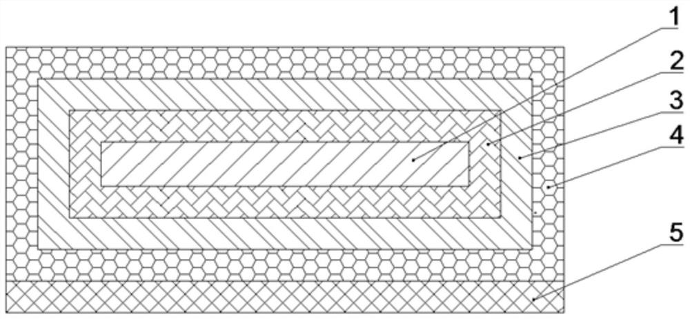
[0083] Such as figure 1 A thermally conductive electrical insulating foam tape for high temperature is shown, which is characterized in that it includes: PET ultra-thin buffer foam layer base material 1, dustproof and heat insulating layer 2, flame retardant layer 3, aluminum foil cloth 4 and embossed Release paper 5; the outer side of the PET ultra-thin buffer foam layer substrate 1 is surrounded by a dust-proof and heat-insulating layer 2; the outer side of the dust-proof and heat-insulating layer 2 is surrounded by a flame-retardant layer 3; the flame-retardant layer 3. An aluminum foil cloth 4 is arranged around the outside; one side of the aluminum foil cloth 4 away from the PET ultra-thin cushioning foam layer substrate 1 is provided with an embossed release paper 5 .

[0084] In addition, the PET ultra-thin cushioning foam layer substrate 1 is formed by the following proportions by weight:

[0085] Waste foam: 15 parts;

[0086] Polyethylene terephthalate: 8 parts;

...

Embodiment 2

[0122] Such as figure 1 A thermally conductive electrical insulating foam tape for high temperature is shown, which is characterized in that it includes: PET ultra-thin buffer foam layer base material 1, dustproof and heat insulating layer 2, flame retardant layer 3, aluminum foil cloth 4 and embossed Release paper 5; the outer side of the PET ultra-thin buffer foam layer substrate 1 is surrounded by a dust-proof and heat-insulating layer 2; the outer side of the dust-proof and heat-insulating layer 2 is surrounded by a flame-retardant layer 3; the flame-retardant layer 3. An aluminum foil cloth 4 is arranged around the outside; one side of the aluminum foil cloth 4 away from the PET ultra-thin cushioning foam layer substrate 1 is provided with an embossed release paper 5 .

[0123] In addition, the PET ultra-thin cushioning foam layer substrate 1 is formed by the following proportions by weight:

[0124] Waste foam: 30 parts;

[0125] Polyethylene terephthalate: 10 parts; ...

Embodiment 3

[0161] Such as figure 1 A thermally conductive electrical insulating foam tape for high temperature is shown, which is characterized in that it includes: PET ultra-thin buffer foam layer base material 1, dustproof and heat insulating layer 2, flame retardant layer 3, aluminum foil cloth 4 and embossed Release paper 5; the outer side of the PET ultra-thin buffer foam layer substrate 1 is surrounded by a dust-proof and heat-insulating layer 2; the outer side of the dust-proof and heat-insulating layer 2 is surrounded by a flame-retardant layer 3; the flame-retardant layer 3. An aluminum foil cloth 4 is arranged around the outside; one side of the aluminum foil cloth 4 away from the PET ultra-thin cushioning foam layer substrate 1 is provided with an embossed release paper 5 .

[0162] In addition, the PET ultra-thin cushioning foam layer substrate 1 is formed by the following proportions by weight:

[0163] Waste foam: 22.5 parts;

[0164] Polyethylene terephthalate: 9 parts; ...


PUM

PropertyMeasurementUnit
diameteraaaaaaaaaa
diameteraaaaaaaaaa
thicknessaaaaaaaaaa

Abstract

The invention discloses a heat-conductive electrical insulating foam tape for high temperature, which comprises: a PET ultra-thin buffer foam layer base material, a dust-proof and heat-insulating layer, a flame-retardant layer, an aluminum foil cloth and an embossed release paper; the PET The outer side of the ultra-thin buffer foam layer substrate is surrounded by a dust-proof and heat-insulating layer; the outer side of the dust-proof and heat-insulating layer is surrounded by a flame-retardant layer; the outer side of the flame-retardant layer is surrounded by aluminum foil cloth; One side of the PET ultra-thin buffer foam layer substrate is provided with embossed release paper. The overall thickness of the base material of the PET ultra-thin cushioning foam layer is 0.25~0.4mm, which makes the polymer foam described in the present invention more able to have light and thin characteristics while blocking insulation and shock resistance, which expands the application range of the foam and solves the problem. practical application needs. The dust-proof and heat-insulating layer can make the foam dust-proof and heat-insulating. The flame retardant layer can make the foam flame retardant.

Description

technical field [0001] The invention belongs to the technical field of foam preparation, and in particular relates to a preparation process of thermally conductive electrical insulation foam tape for high temperature. Background technique [0002] Foam is a material made of foamed plastic particles, referred to as foam. Foam is divided into PU foam, anti-static foam, conductive foam, EPE, anti-static EPE, PORON, CR, EVA, bridging PE, SBR, EPDM, etc. Foam has a series of characteristics such as elasticity, light weight, fast pressure-sensitive fixation, convenient use, free bending, ultra-thin volume, and reliable performance. It is mainly used in electronic products, military industry, and aerospace fields. [0003] Currently, there are mainly the following problems: [0004] 1. Traditional PE, PU and melamine foam have good cushioning and insulation properties, but due to the limitation of processing technology, it is impossible to obtain a high foaming ratio and ultra-th...

Claims


Application Information

Patent Timeline
Patent Type & Authority Patents(China)
IPC IPC(8): C09J7/29C09J7/30C09J183/07C09J11/06C09J11/08C08L75/04C08L67/02C08L101/00C08K5/01C08L23/08C08K3/013C08K3/22C08K3/26C08K3/32D06M11/71D06M11/45D06M11/47D06M11/44D06M13/358D06M11/82D06M13/262
Inventor 黄林妹俞希达吴婷
Owner 苏州泰富金电子科技有限公司
Why Eureka
Try Eureka