Linear motor generator power supply

A linear motor, power supply technology, applied in electrical components, electromechanical devices, etc., can solve the problems of low power density and application value, consumption of petroleum energy, etc.

Inactive Publication Date: 2019-06-04
裘根富
View PDF1 Cites 4 Cited by
  • Summary
  • Abstract
  • Description
  • Claims
  • Application Information

AI Technical Summary

Problems solved by technology

[0005] Prior art documents: CN201510217219 a star-shaped electromagnetic power generator, CN200680002098 improved tubular generator, US3576458 HEAVY DUTY OVERVOLTAGE POWER GAP and the free piston engine linear generator developed by Toyota. However, the mechanical transmission of permanent magnet pistons has relatively l

Method used


Image

  • Linear motor generator power supply
  • Linear motor generator power supply
  • Linear motor generator power supply

Examples


specific Embodiment 1

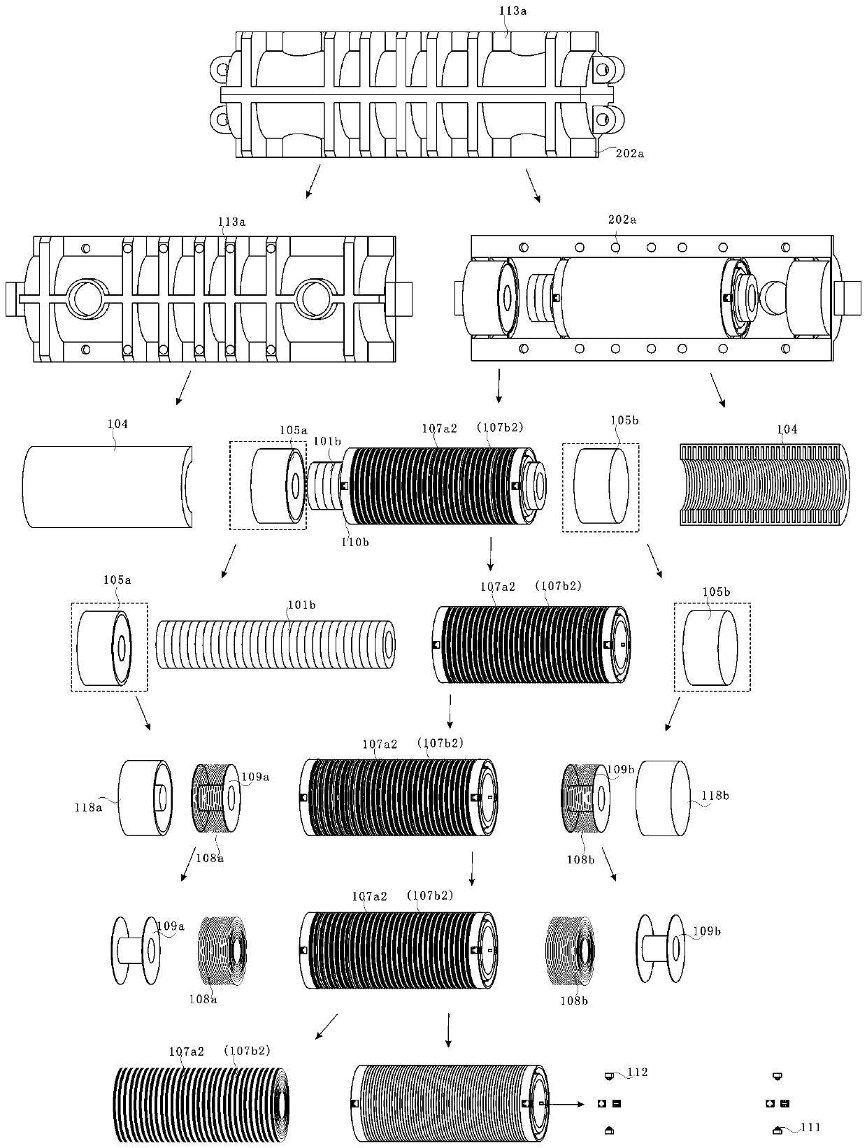
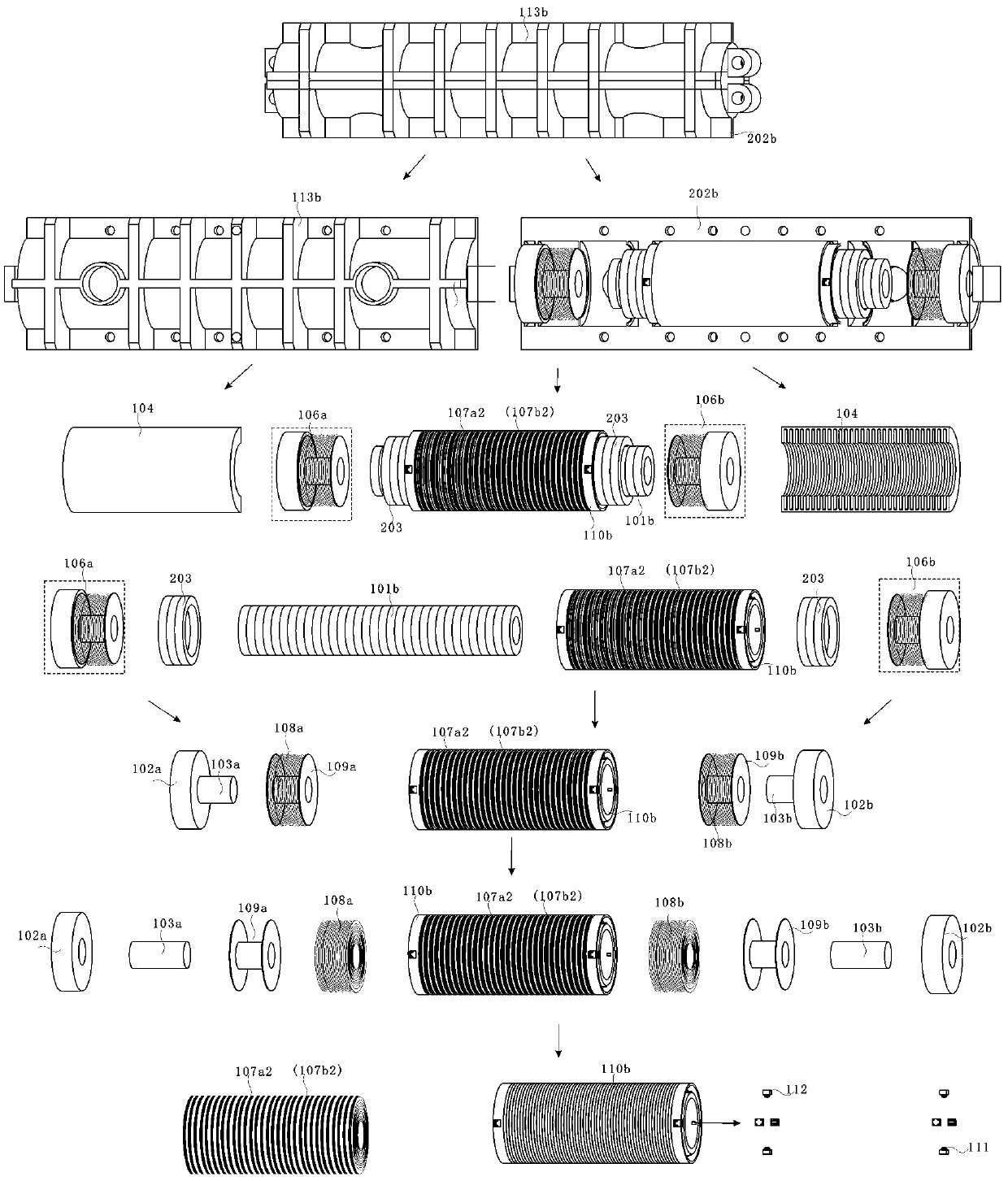
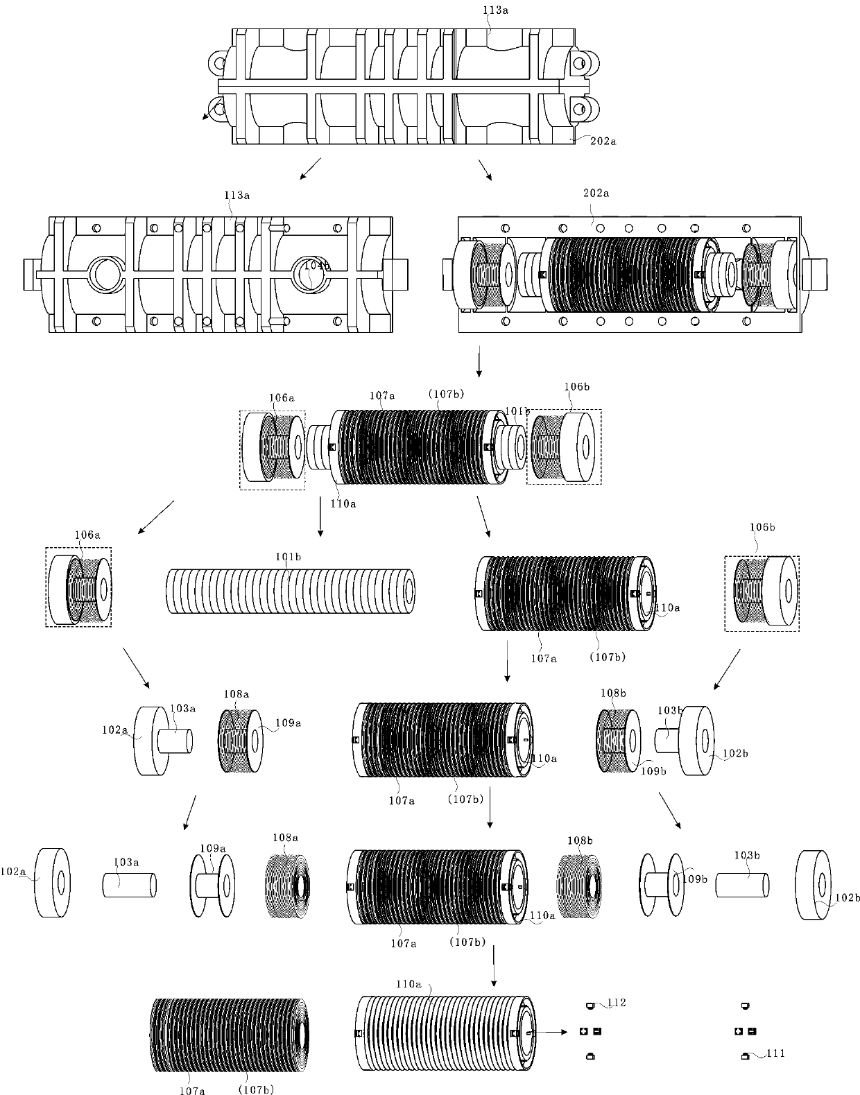
[0072] Specific embodiment one (see Figure 1-4 ) assembly assembly process steps are.

[0073] Step 1: 8 ceramic bearings are embedded in the inner wall of the two ends of the winding skeleton 110 cylinder, and 4 of each end form an angle of 90 degrees; Coaxial, the gland 112 is pressed on the ceramic bearing shaft, and the gland 112 is provided with a screw hole and fastened with the winding frame 110 to form a guide roller.

[0074] Step 2: The winding frame 110a has a plurality of annular grooves, and the non-stator windings 107a and b are sequentially embedded, and the outer peripheral surfaces of the non-stator windings 107a2 and b2 are resin-filled to form the non-stator windings 107a and b.

[0075] Step 3: Stator windings 107a2 and b2 are sequentially embedded in a plurality of circular grooves in the winding frame 110b, and the outer peripheral surfaces of the stator windings 107a2 and b2 are resin-filled to form no stator windings 107a2 and b2.

[0076] Step 4: Wi...

specific Embodiment 2

[0084] Specific embodiment two, ( Image 6 , 7 and 8) Linear motor generator drive mode 1, dual control bidirectional Buck-BoostDC / DC converters VT20, VT21, VT10, VT11 are turned on and VT19, VT22, VT9, VT12 are turned off, and the super capacitor module has 304 DC directions Bus discharge, supercapacitor module 305 charging, single-phase inverter circuit VT2, VT3, VT5, VT8 off, pulse-type alternate conduction on VT1, VT4 and VT6, VT7, excitation coil 108a or b is energized and driven, forcing the permanent magnet The array free piston mover 101 reciprocates axially, the bidirectional thyristors U1, U2 and U3, U4 alternately control the rectification and isolation circuits 302a and 302b, the excitation coil 108a or 108b and the stator winding 107a or 107a2 generate an induced current, which is output through rectification and filtering. The two-way Buck-Boost DC / DC converter is controlled by joint connection busbars to charge the supercapacitor module 305; when the voltage of ...

specific Embodiment 3

[0085] Specific embodiment three, ( Image 6 , 7 And 8) Linear motor generator drive mode 2, dual control bidirectional Buck-BoostDC / DC converter VT20, VT21, VT10, VT11 on and VT19, VT22, VT9, VT12 off, super capacitor module 304 directions Bus discharge, supercapacitor module 305 charging, three-phase inverter circuit VT13-VT18 IGBT tube phase sequence two-two pulse conduction stator winding 107b and single-phase inverter circuit VT1-VT8 off, forcing the permanent magnet array free piston The mover 101 is suspended and reciprocated in the axial direction, the bidirectional thyristors control the rectification circuits U1, U2 and U3, U4 and U5, U6 and U7, U8 and U9, and U10 alternately control the rectification and isolation circuits 302a or 302b and 309, 310 or 311, and the excitation coil 108a or 108b, the stator winding 107a or 107a2, and one phase of the stator winding 107b or b2 generate an induced current, output it through rectification and filtering, and jointly connec...


PUM


Abstract

The invention provides a linear motor generator power supply which comprises double electromagnets placed at two ends of a body, and a tubular linear generator is placed in the middle to form two cylinders A and B. An electromagnet excitation coil a is energized to force a permanent magnet array free piston mover to perform mechanical movement to the B cylinder, therefore, magnetic lines cut a linear generator stator winding and an electromagnet excitation coil b, induced current is generated, a group of super capacitor modules is charged after rectification and voltage regulation, another group of super capacitor modules discharges to the electromagnet excitation coil a, and balance current is used for a load. Conversely, the electromagnet excitation coil b is energized, the linear generator stator winding and the electromagnet excitation coil a generate induced current, the electromagnet excitation coil a or b is alternately conducted in a pulse way, and the linear generator stator winding and the electromagnet excitation coil a or b generate continuous induced current. The two groups of super capacitor modules are alternately and automatically switched between charging and discharging, the voltage cycle, conversion and recombination required for linear motor generator driving can be achieved, balance voltage is outputted from the load. The linear motor generator of the present invention provides a regenerable power source.

Description

technical field [0001] The invention relates to the technical fields of new energy, regenerative power supply, motor and generator, in particular to a linear motor generator power supply, which becomes a renewable power supply. Background technique [0002] The accompanying energy security and environmental pollution are two of the most thorny bottlenecks. Petroleum security, resource shortage, and harmful substances emitted by the exhaust of automobiles during driving damage the environment and human health. [0003] However, electric vehicles have hybrid, plug-in hybrid, fuel cell, pure electric vehicles and other modes, limited by the level of power battery technology and charging technology, there are energy density, cruising range, charging speed, construction of charging stations, etc. Restricting factors have become a bottleneck in the development of pure electric vehicles. In view of this, there is an urgent need for a generator or charging method for renewable power...

Claims


Application Information

Patent Timeline
IPC IPC(8): H02K53/00
Inventor 裘根富
Owner 裘根富
Why Eureka
Try Eureka