Ultraviolet irradiation device for cable curing

An external irradiation and cable technology, applied in the field of light curing, can solve the problems of low utilization efficiency of light irradiation, uneven curing, high working power, etc., to improve the use efficiency and irradiation uniformity, ensure product quality stability, improve The effect of production speed

Pending Publication Date: 2019-06-07
南京新趋势光电有限公司
View PDF10 Cites 3 Cited by
  • Summary
  • Abstract
  • Description
  • Claims
  • Application Information

AI Technical Summary

Problems solved by technology

However, there are many disadvantages in the UV mercury lamp tube: high working power, short service life (800 hours to 1500 hours), strong pollution (ozone generated during work affects human health, and thermal effect will cause volatile organic compounds to be produced in cured coatings. The lamp tube will cause mercury pollution), inconvenient to use (starting requires preheating, closing requires heat dissipation), etc.
Since the UV LED emits light in a Lambertian distribution, the closer to the center, the denser the light. With symmetrical placement, the densest part of the light will directly irradiate the opposite UV LED light source module, which cannot be reflected by the reflector next to it. , resulting in low utilization efficiency of light irradiation and uneven curing

Method used


Image

  • Ultraviolet irradiation device for cable curing
  • Ultraviolet irradiation device for cable curing
  • Ultraviolet irradiation device for cable curing

Examples


Embodiment 1

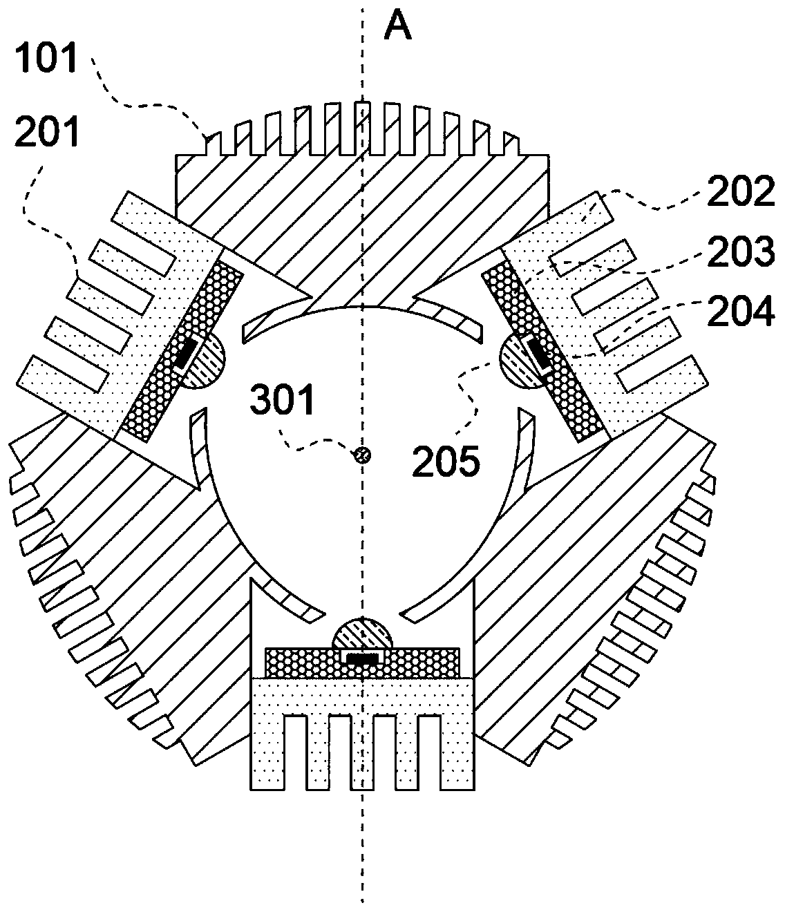
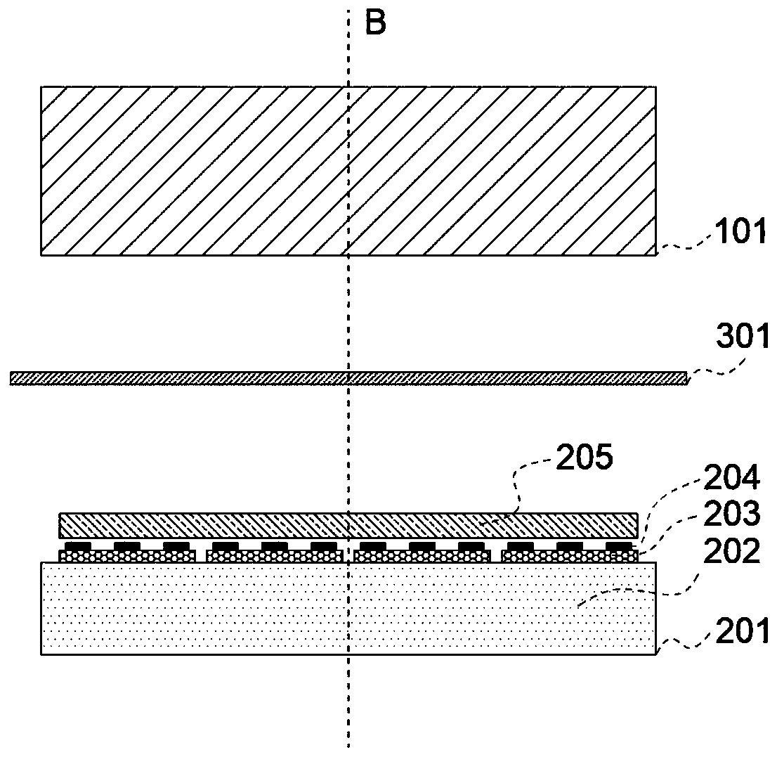
[0047] see figure 1 and figure 2 , figure 1 It is an assembly structure diagram of the ultraviolet irradiation device used for cable curing in this embodiment, figure 2 for along figure 1 The cross-sectional view of the A-axis in the middle, while figure 1 also along figure 2 Sectional view of the middle B axis. An ultraviolet irradiation device for cable curing includes 3 reflector modules 101 and 3 UV LED light source modules 201, the reflector modules 101 and UV LED light source modules 201 are alternately arranged to form a structure with an opening in the middle (i.e. the aforementioned Opening area, the same below), the object to be irradiated 301 is located in the center of the opening structure.

[0048] Wherein, the material of the reflector module 101 is aluminum alloy, and its side facing away from the middle opening structure is a fin structure that facilitates heat dissipation, and its surface facing the opening structure side is a polished arc surface, a...

Embodiment 2

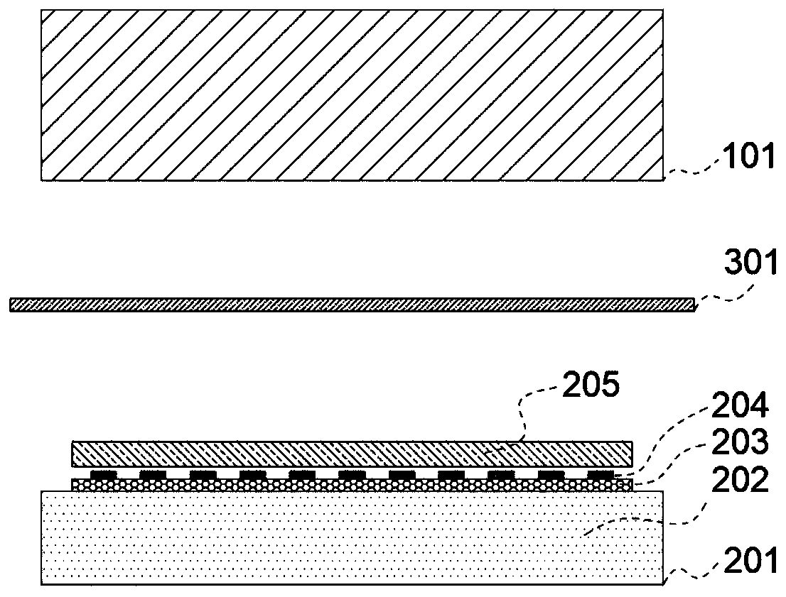
[0052] like image 3 As shown, an ultraviolet irradiation device for cable curing, its main structure is the same as that of embodiment 1, the difference is that in this embodiment, in order to improve the integration of products and the ease of installation, each UV LED light source module 201 Only one substrate 203 is included, and eleven chips 204 will be mounted on the same substrate 203 to form a COB-shaped UV LED lamp bead, and each UV LED light source module 201 contains only one COB-shaped UV LED lamp bead.

Embodiment 3

[0054] see Figure 4 and Figure 5 , this embodiment discloses another embodiment of the ultraviolet irradiation device, Figure 4 It is the assembly structure drawing of this embodiment, Figure 5 for along Figure 4 The cross-sectional view of the A-axis in the middle, while Figure 4 also along Figure 5 Sectional view of the middle B axis.

[0055] Specifically, an ultraviolet irradiation device for cable curing includes three reflector modules 111 and three UV LED light source modules 211, and the reflector modules 111 and UV LED light source modules 211 are alternately arranged to form a structure with an opening in the middle The ring device, the object 301 to be irradiated is located in the center of the opening structure.

[0056] Wherein, the reflector module 111 is made of stainless steel, and its side facing away from the opening structure is a fin structure that is good for heat dissipation, and its side facing the opening structure is a long groove shape, a...


PUM


Abstract

The invention discloses an ultraviolet irradiation device for cable curing. The ultraviolet irradiation device comprises a complex number of ultraviolet light source components and a complex number ofmirror components, and the ultraviolet light source components and the mirror components are arranged around a designated area; the ultraviolet light source components and the mirror components are arranged in sequence alternately, and all the light emission ends of the ultraviolet light source components and the reflective surfaces of the mirror components face the designated area; and when an irradiated object is placed in the designated area, a part of ultraviolet light emitted from any ultraviolet light source component can directly penetrate into a first area of the irradiated object, and the other part of the ultraviolet light can be reflected by at least one reflection component to areas beyond the first area in the irradiated object. According to the ultraviolet irradiation devicefor cable curing, the use efficiency and irradiation uniformity of UV-LED irradiation light can be improved, and the coating and coloring production rate of optical fiber cables can be improved effectively, and reaches 3000 m / min and above; and the product quality stability in the high speed production process can be ensured.

Description

technical field [0001] The invention particularly relates to an ultraviolet irradiation device for cable curing, which belongs to the field of light curing technology. Background technique [0002] Due to its excellent performance and meeting people's ever-increasing environmental protection needs, UV-curable coatings have been more and more widely used in various fields, such as paper, wood, plastics, metals, optical discs, optical fibers and other substrates. use effect. UV curing coatings need to be cured by UV light irradiation, generally using UV mercury lamps. However, there are many disadvantages in the UV mercury lamp tube: high working power, short service life (800 hours to 1500 hours), strong pollution (ozone generated during work affects human health, and thermal effect will cause volatile organic compounds to be produced in cured coatings. The lamp tube will cause mercury pollution), inconvenient to use (it needs to be preheated when it is started, and it need...

Claims


Application Information

Patent Timeline
Patent Type & Authority Applications(China)
IPC IPC(8): B05D3/06
Inventor 蔡云峰王生健许朝军周玉刚
Owner 南京新趋势光电有限公司
Why Eureka
Try Eureka