Numerical control direct-drive type electric screw press

An electric screw and direct drive technology, applied in the field of screw pressure equipment, can solve the problems of hidden safety hazards in the operation process, cumbersome and complicated process, locking of the main screw drive pair, etc., and achieve the effect that the positioning is difficult to be accurate

Pending Publication Date: 2019-06-07
WUHAN NEWWISH TECH
View PDF10 Cites 2 Cited by
  • Summary
  • Abstract
  • Description
  • Claims
  • Application Information

AI Technical Summary

Problems solved by technology

[0004] (1) The output torque of the main motor is transmitted to the small gear through the friction clutch, and then to the large gear. The transmission chain is relatively complicated
[0005] (2) Axial clearance adjustment is very cumbersome and inefficient: first remove the ordinary flat key block, then remove the lock nut, then remove all the screws with a large number of pressure rings, then remove the pressure ring, and then pad the slider to lift For the main screw, use a meter to check the wear data of the thrust bearing, and calculate the thickness of the required adjustment gasket. The process is cumbersome and complicated, and there are safety hazards in the operation process
[0006] (3) The main screw and the main nut are lubricated with grease, which has high viscosity, slow heat dissipation, and insufficient lubrication, resulting in high friction, aggravating the wear of the copper alloy main nut, affecting the transmission efficiency, and causing the temperature of the screw and nut to rise, and parts to expand and deform. , and even lockup and damage of the main screw transmission pair
Since the motor works under the condition of high current and high torque for a long time, and starts and brakes frequently, the traditional air cooling device cannot reduce the heat dissipation problem of the motor. If the motor overheats, the efficiency will be reduced, the alarm will stop, and even the motor will be burned, and the production line will be shut down. Wait for a series of questions

Method used


Image

  • Numerical control direct-drive type electric screw press
  • Numerical control direct-drive type electric screw press
  • Numerical control direct-drive type electric screw press

Examples


Embodiment Construction

[0054] In order to make the object, technical solution and advantages of the present invention clearer, the present invention will be further described in detail below in conjunction with the accompanying drawings and embodiments. It should be understood that the specific embodiments described here are only used to explain the present invention, not to limit the present invention. In addition, the technical features involved in the various embodiments of the present invention described below can be combined with each other as long as they do not constitute a conflict with each other.

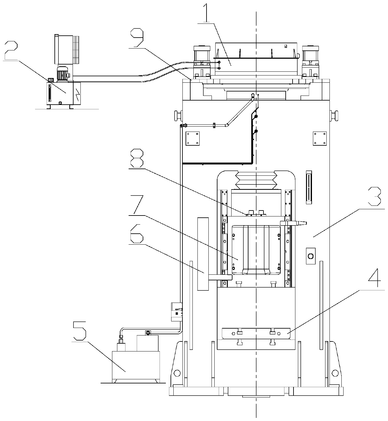
[0055] like figure 1 As mentioned above, the embodiment of the present invention provides a numerical control direct-drive electric screw press, including a motor 1, a cooling system 2, a body 3, a workbench backing plate 4, a lubrication system 5, a stroke encoder 6, a slider 7, Buffer device 8 and gap adjustment mechanism 9. Wherein, the motor 1 is arranged on the top of the fuselage 3 and i...


PUM


Abstract

The invention discloses a numerical control direct-drive type electric screw press which comprises a machine body (3), a motor (1) arranged on the top of the machine body (3), a slider (7) arranged inthe machine body (3), a workbench backing plate (4) arranged at the bottom of the slider (7), a lubricating system (5) and a clearance adjusting mechanism (9); the outer side of the motor (1) is provided with a cooling system (2); and the clearance adjusting mechanism (9) comprises a power transmission unit and a clearance adjusting unit and is used for converting rotary motion to linear motion of the slider (7). For the screw press, an axial clearance of a main screw rod can be accurately adjusted by the clearance adjusting mechanism, rapid real-time circulation cooling of the motor is realized with the cooling system, the lubricating system realizes full lubrication between the main screw rod and a main nut, the motor directly drives a flywheel to rotate for accumulation of energy, androtating motion of the flywheel is converted to up-down linear motion of the slider by a screw pair so as to realize compression forging formation of a part.

Description

technical field [0001] The technical field of screw press equipment of the present invention, more specifically, relates to a numerically controlled direct-drive screw press, which is widely used in the manufacturing fields of automobiles, high-speed railway locomotives, engineering machinery, ships, and aerospace. Background technique [0002] As die forging equipment, compared with die forging hammers and hot die forging presses, screw presses have the advantages of simple structure, convenient use and maintenance, and a wide range of process applications, while CNC direct drive electric screw presses and friction presses, Compared with other forms of screw presses such as hydraulic screw presses, it has the characteristics of low noise during operation, higher strike times, and accurate and stable control of its strike energy. Therefore, it is widely used in automobiles, high-speed railway locomotives and aerospace industries industry has been widely used. [0003] At pr...

Claims


Application Information

Patent Timeline
Patent Type & Authority Applications(China)
IPC IPC(8): B21J9/06B21J9/18H02K9/19F16H57/04F16H25/24
Inventor 冯仪余俊陈刚余来胜曹超郝思陈志林
Owner WUHAN NEWWISH TECH
Why Eureka
Try Eureka