Electric vehicle thermal management system and control method thereof

A thermal management system and technology for electric vehicles, which are applied in the thermal management system of electric vehicles and their control fields, can solve the problems that heat cannot be recycled each other, the battery cooling demand is weak, and the heating demand is strong, so as to achieve good heating or cooling effect and improve The effect of energy utilization and easy control

Inactive Publication Date: 2019-06-07
DONGFENG MOTOR CORP HUBEI
View PDF5 Cites 9 Cited by
  • Summary
  • Abstract
  • Description
  • Claims
  • Application Information

AI Technical Summary

Problems solved by technology

Since the motor system generally only needs to dissipate heat, a wide design scheme is to connect the motor and related controllers, chargers, etc. in series, and then dissipate heat through the radiator and fan at the front of the vehicle; the battery pack system needs to meet both cooling and heating requirements Generally, an electric heater and a heat exchanger connected to the air-conditioning refrigerant circuit are installed in the coolant circuit of the battery pack to heat and cool the battery. For some vehicles with low ambient temperature, the cooling demand of the battery is relatively weak. The demand for heating is strong, and there is no need to use a refrigerant circuit to cool down the battery pack. The traditional thermal management system has a complex structure and high manufacturing cost; and the heat between the battery and the motor cannot be recycled and reused, and a lot of heat energy is wasted at low temperatures.
[0004] In addition, the operating environment of electric vehicles has a large temperature span, and the properties of existing coolants will vary greatly under high and low temperature conditions. In order to ensure the safety of related vehicles, it is necessary to optimize the design of the water cooling circuit and the control strategy of each component. , to precisely control the flow and temperature of each branch of the cooling system

Method used


Image

  • Electric vehicle thermal management system and control method thereof

Examples


Embodiment Construction

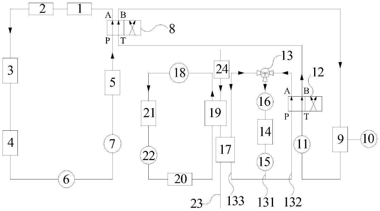
[0023] The present invention will be further described in detail below in conjunction with the accompanying drawings to facilitate a clearer understanding of the present invention, but they do not limit the present invention.

[0024] Such as figure 1 As shown, an electric vehicle thermal management system is designed for a certain model, including a motor cooling system, a battery thermal management system and a PTC electric heating system. The motor cooling system and the battery thermal management system are connected through the first reversing device 8, and the PTC The electric heating system and the battery thermal management system are connected through the second reversing device 12. When the first reversing device 8 and the second reversing device 12 are powered off, they are both in the non-reversing state, and the systems are independent circulation. In the commutation state, the battery thermal management system can be connected in series with the motor cooling sys...


PUM


Abstract

The invention discloses an electric vehicle thermal management system, being characterized by including a motor cooling system, a battery thermal management system and a PTC electric heating system. The motor cooling system is connected with the battery thermal management system through a first steering device, the PTC electric heating system is connected with the battery thermal management systemthrough a second steering device. The electric vehicle thermal management system further includes an air conditioning system and a circulating air duct, the circulating air duct is sequentially connected with an evaporator and a warm air core in series, two reversing solenoid valves and a proportional three-way valve are used to control the connection among the battery thermal management system,the motor cooling system and the PTC electric heating system. The system is simple in structure and easy to control. The invention also discloses a control method of the electric vehicle thermal management system. The method can switch between six working modes according to the ambient temperature and the working temperature of a battery pack, utilize the energy of each system to complement each other, and improve the energy utilization rate of the thermal management system.

Description

technical field [0001] The invention belongs to the technical field of electric vehicles, and specifically refers to an electric vehicle thermal management system and a control method thereof. Background technique [0002] Batteries, motors, and related controllers are the main heating elements of pure electric vehicles. In high-temperature environments, the above-mentioned components need to be cooled to ensure the safety of the vehicle. In low-temperature environments, heating and heat preservation are required to improve vehicle performance. and energy efficiency, while in order to ensure the thermal comfort of the occupants, it is necessary to heat and cool the occupant compartment. [0003] Currently, most electric vehicles use a water-cooled thermal management system. Since the motor system generally only needs to dissipate heat, a wide design scheme is to connect the motor and related controllers, chargers, etc. in series, and then dissipate heat through the radiator...

Claims


Application Information

Patent Timeline
Patent Type & Authority Applications(China)
IPC IPC(8): B60H1/00B60H1/03B60H1/14B60K11/04B60L58/26B60L58/27
CPCY02T10/70
Inventor 徐人鹤王小碧王伟民王希诚屈新田
Owner DONGFENG MOTOR CORP HUBEI
Why Eureka
Try Eureka