Flexible capacitive sensor based on conductive rubber

A capacitive sensor, conductive rubber technology, applied in instruments, measuring devices, measuring forces, etc., can solve problems such as difficulty in evaluating performance, complex processes, and cumbersome processes, and achieve good process integrity, safe preparation conditions, and sample extension. high rate effect

Active Publication Date: 2019-06-14
BEIJING UNIV OF TECH
View PDF9 Cites 8 Cited by
  • Summary
  • Abstract
  • Description
  • Claims
  • Application Information

AI Technical Summary

Problems solved by technology

The limitations of this patent: 1) The electrode pattern prepared by the photolithography process is complicated, and the cleaning of the photoresist leads to large emissions and high cost
2) The metal electrode is an inflexible material. Although it is attached to the flexible rubber, its overall structure is an incompletely flexible material.
3) The lack of test data of sensor performance in the patent statement makes it difficult to evaluate its performance
The limitations of this patent: 1) The metal electrode is prepared by photolithography process, which is cumbersome and polluting; 2) The metal electrode is a non-flexible material. Although it is attached to the LCP flexible substrate, the overall structure is still an incompletely flexible material. , and the affinity between the metal film and the LCP substrate is average, and the wearability is poor; 3) The graphene oxide contained in the dielectric layer used has low output and high price
The limitations of this patent: 1) The conductive metal film is pasted on the elastic insulating film as the electrode layer, which is not a fully flexible material, and the specific material used is not reported in the patent; 2) The interdigitated array structure is passed through photolithography Prepared by the method, the process steps are complic

Method used


Image

  • Flexible capacitive sensor based on conductive rubber
  • Flexible capacitive sensor based on conductive rubber
  • Flexible capacitive sensor based on conductive rubber

Examples


example 1

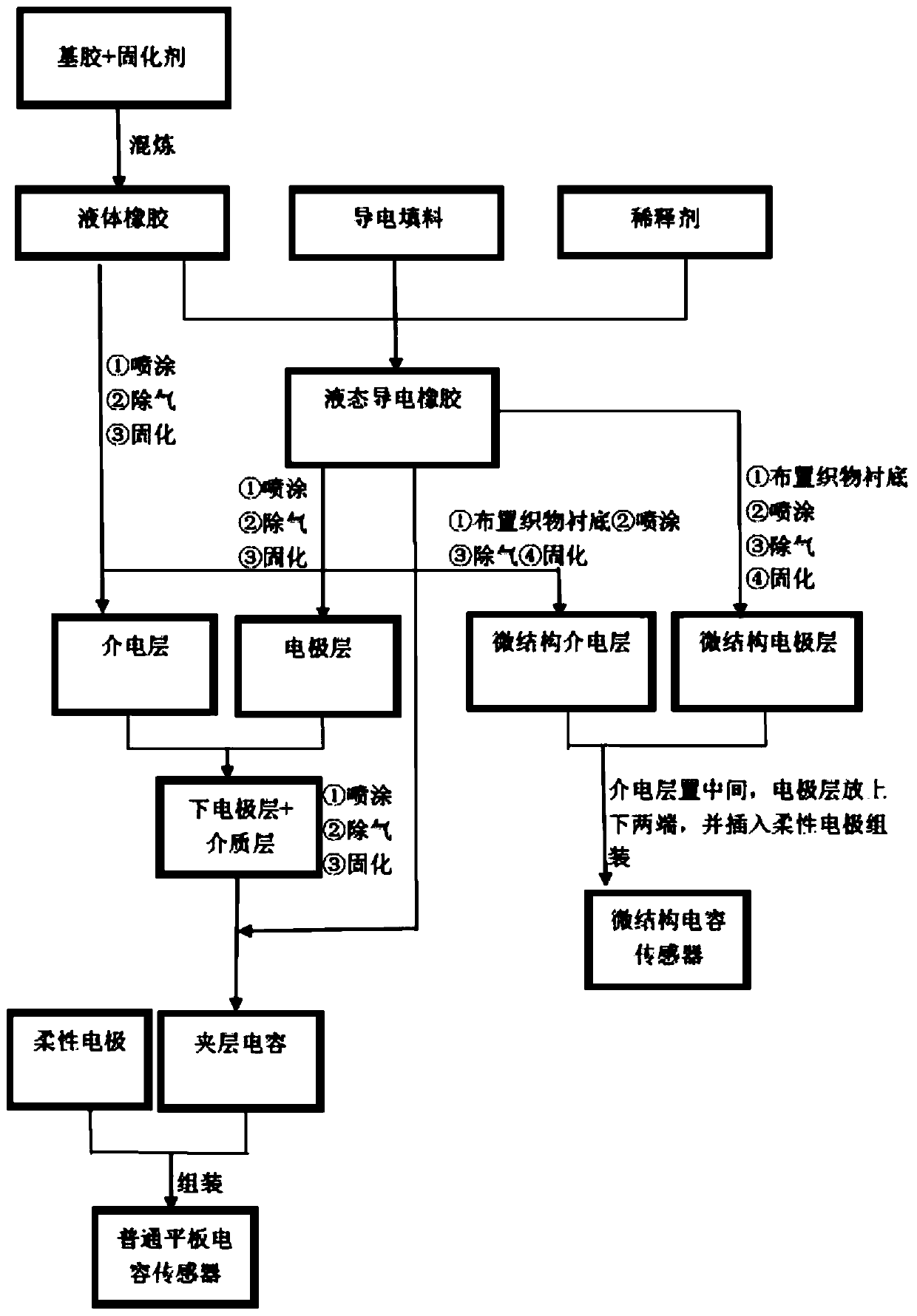
[0053] The liquid pure rubber formula is mixed with 80wt% PDMS and 20wt% Dow Corning 184B curing agent. The viscosity of the liquid pure rubber after mixing is 1100mPa s; the liquid conductive rubber formula is 60wt% PDMS, 10wt% Dow Corning 184B curing agent, and 20wt% nickel-coated carbon fiber filler (The length of the nickel-coated carbon fiber is 110 μm, and the diameter is 12 μm) is mixed with 10 wt % simethicone diluent, and the viscosity of the liquid conductive rubber after mixing is 1000 mPa·s. The preparation is carried out according to the following steps: ① Preparation of the first electrode layer, put the liquid conductive rubber into the spray gun, spray it on the PET film at a pressure of 0.7MPa, and further perform vacuum degassing under the environment of -0.1MPa for 10min, and finally place it at 150°C 5min curing and forming; ②dielectric layer preparation, put pure liquid rubber into the spray gun, and spray it on the first electrode layer prepared in ① under...

example 2

[0056] The liquid pure rubber formula is mixed with 90wt% PDMS and 10wt% Dow Corning 184B curing agent; the viscosity of the liquid pure rubber after mixing is 1300mPa s; the liquid conductive rubber formula is 40wt% PDMS, 10wt% Dow Corning 184B curing agent, and 30wt% nickel-coated carbon fiber filler (Nickel-coated carbon fiber with a length of 95 μm and a diameter of 10 μm) is mixed with 20 wt % simethicone diluent, and the viscosity of the liquid conductive rubber after mixing is 1080 mPa·s. Preparation is carried out according to the following steps: ① Preparation of the first electrode layer, put the liquid conductive rubber into the spray gun, spray it on the PET film at a pressure of 0.7MPa, and further perform vacuum degassing under the environment of -0.1MPa for 10min, and finally place it at 150°C 5min curing and forming; ②dielectric layer preparation, put pure liquid rubber into the spray gun, and spray it on the first electrode layer prepared in ① under the pressur...

example 3

[0059] The liquid pure rubber formula is 85wt% PDMS, mixed with 15wt% Dow Corning 184B curing agent. Filler (nickel-coated carbon fiber with a length of 130 μm and a diameter of 17 μm) was mixed with 15 wt % simethicone diluent, and the viscosity of the liquid conductive rubber after mixing was 900 mPa·s. The preparation was carried out according to the following steps: ① Arrange two hydrophobic cloth substrates with microstructures on the surface. The surface of the hydrophobic cloth has a fibrous knot-like texture, the width of the fibrous knots is 100 μm, and the height of the knots is 15 μm. ② Spray the electrode layer, put the liquid conductive rubber into the spray gun, spray it on the first substrate under the pressure of 0.7MPa, carry out vacuum degassing at -0.1MPa for 10min, and further, place it at 150℃ for 7min Curing; ③Spray the dielectric layer, put the liquid pure rubber into the spray gun, spray it on the second substrate under the pressure of 0.7MPa, carry out...


PUM

PropertyMeasurementUnit
Lengthaaaaaaaaaa
Total thicknessaaaaaaaaaa
Lengthaaaaaaaaaa

Abstract

The invention provides a flexible capacitive sensor based on conductive rubber. According to the sensor, flexible conductive rubber is used as a conductive pole plate, flexible pure rubber is used asa dielectric layer, a spraying process is utilized to prepare all layers of the capacitive sensor, and a surface microstructure is used as assistance. The prepared flexible capacitive sensor makes a remarkable signal response to an external load and can be used for stretching, compression and movement tests, wherein the pure rubber of the dielectric layer is prepared by mixing 80-90wt% of liquid rubber and 10-20wt% of a curing agent; the conductive rubber is prepared by mixing 40wt%-60wt% of liquid rubber, 10-15wt% of a curing agent, 20wt%-30wt% of a conductive filler and 10-20wt% of a diluent; and through layered spraying and step-by-step or overall curing, the flexible capacitive sensor with a good mechanical signal response is obtained. According to the capacitor, the conductive pole plate layer is conductive rubber, the dielectric layer is pure liquid rubber, and therefore the capacitor is a complete flexible sensor in a true sense.

Description

technical field [0001] The invention relates to a flexible capacitive sensor based on conductive rubber, and the flexible capacitor prepared by it can be used as an electronic element and a sensor device, and belongs to the field of electronic equipment. Background technique [0002] Flexible electronic devices have broad prospects in the current development, such as flexible smartphones, electronic skin, wearable health detectors and other fields. At present, flexible electronic devices are mostly used in the field of sensors. Connect the sensor to the matching circuit and signal processor, and under the external load and specific environment, the electrical performance of the flexible sensor will change, so as to achieve the effect of signal feedback. Flexible sensors have great development potential in the fields of wearable electronic materials and future human-computer interaction, mainly capacitive and resistive sensors. Flexible capacitive sensors often use pure rub...

Claims


Application Information

Patent Timeline
IPC IPC(8): G01L1/14G01L1/22C08L83/04C08L47/00C08L83/07C08K9/10C08K9/02C08K3/04C08K7/06C08K3/08C08K7/14
Inventor 夏志东高沐王雪龙高园林健
Owner BEIJING UNIV OF TECH
Why Eureka
Try Eureka