Pipeline dredging robot

A robot and pipeline technology, applied in the field of pipeline dredging, can solve problems such as easy to be blocked, unstable work, excessive sewage flow, etc., and achieve the effect of preventing internal blockage, reducing labor intensity, and strong applicability

Pending Publication Date: 2019-06-25
IANGSU COLLEGE OF ENG & TECH
View PDF0 Cites 5 Cited by
  • Summary
  • Abstract
  • Description
  • Claims
  • Application Information

AI Technical Summary

Problems solved by technology

If the pipeline is not regularly dredged, it will cause excessive sewage flow, pollute the environment, and bring troubles to people's lives
[0003] However, the traditional pipeline dredging equipment has the disadvantages of being easily blocked, unstable work, incomplete dredging, and the need to manually push along the inner wall of the pipeline, which seriously increases the labor intensity of the staff. The shortcoming of weak applicability to dredging pipelines with different diameters, for this reason, a pipeline dredging robot is proposed

Method used


Image

  • Pipeline dredging robot
  • Pipeline dredging robot
  • Pipeline dredging robot

Examples


Embodiment 1

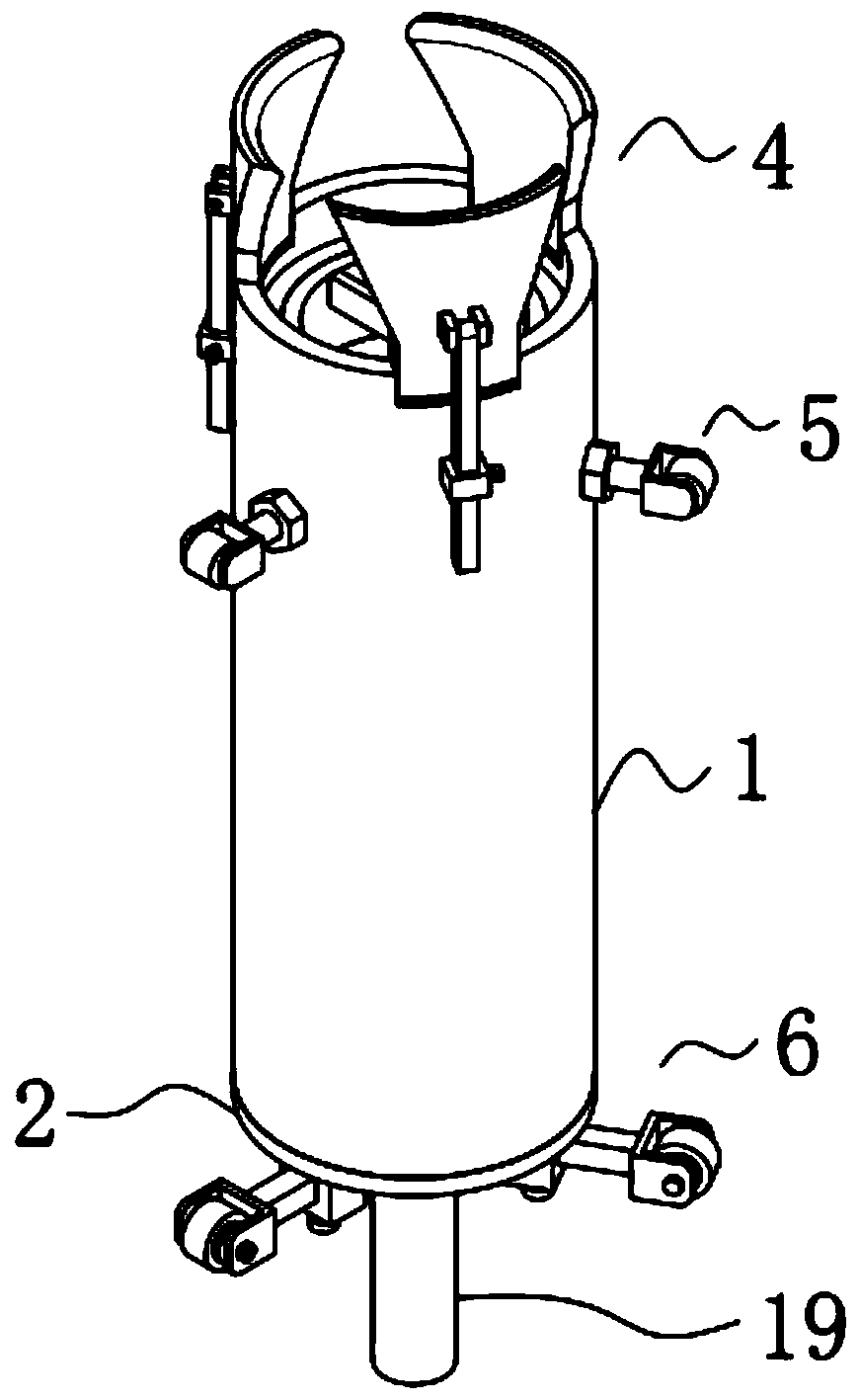
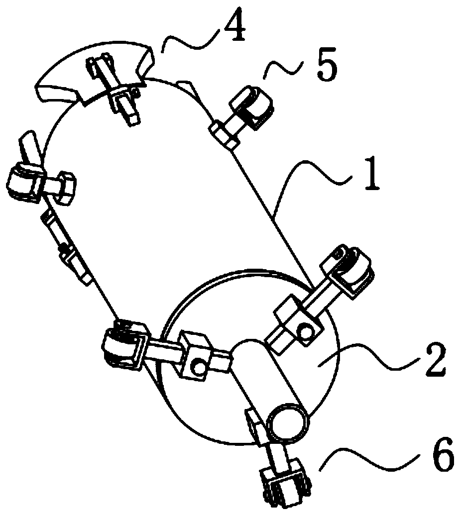
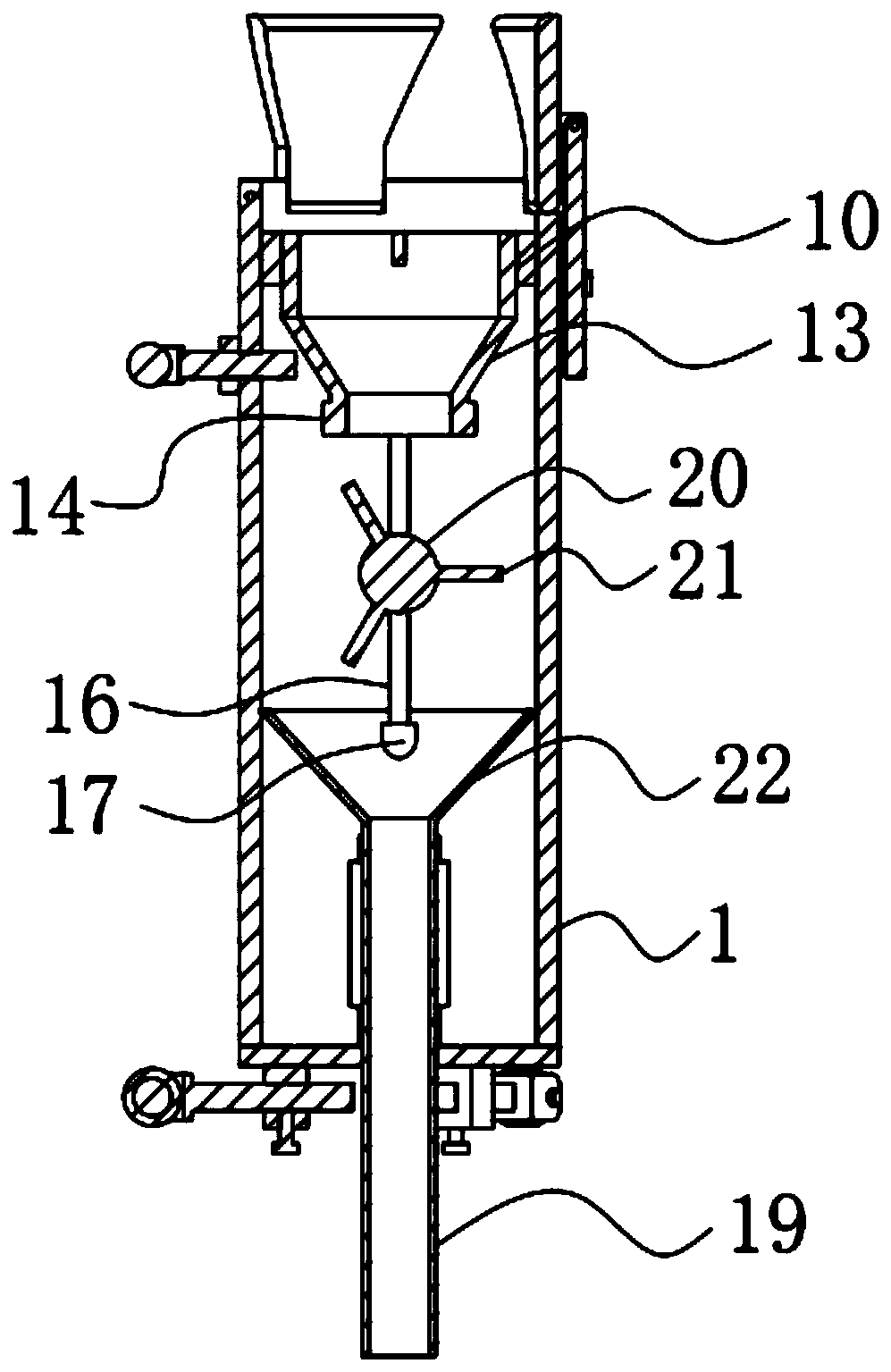
[0055] A pipeline dredging robot, such as Figure 1-2 As shown, it includes a cylindrical shell 1, the upper end of the cylindrical shell 1 is evenly provided with at least three sets of scraper assemblies 4, and the bottom end of the cylindrical shell 1 is fixedly equipped with an end cover 2, the cylindrical shell 1 At least three sets of support assemblies 5 are evenly provided on the outer surface of the outer surface near its upper end, and at least three sets of crawling assemblies 6 are evenly provided on the side of the end cover 2 away from the cylindrical shell 1. A crushing assembly 18 is provided inside the casing 1 near its upper end, and a sludge discharge assembly 3 is provided inside the cylindrical casing 1 near the crushing assembly 18 .

[0056] By adopting the above-mentioned technical scheme, the scraper assembly 4 is used to scrape off the dirt on the inner wall of the pipeline that needs to be cleaned; the crushing assembly 18 is used to crush the dirt s...

Embodiment 2

[0077] The difference from Embodiment 1 is that the surfaces of the first brushless motor 38, the second brushless motor 20 and the drive motor 12 are all provided with a protective layer, and the protective layer is prepared by the following method:

[0078] Take the following raw materials and weigh them by weight: 25 parts of epoxy resin, 10 parts of calcium carbonate powder, 25 parts of acrylic emulsion, 10 parts of quartz powder, 12 parts of polyurethane, 10 parts of asphalt, 3 parts of alcohol ester twelve, 2 parts of emulsified silicone oil , 20 parts of triethanolamine and 20 parts of water;

[0079] S1. Add the weighed acrylic emulsion, asphalt, alcohol ester dodeca, triethanolamine, emulsified silicone oil and ethanol into the mixer and stir for 20min at a stirring speed of 600r / min to prepare a mixed solution;

[0080] S2, adding epoxy resin, calcium carbonate powder, quartz powder and polyurethane into a pulverizer for pulverization until the particle diameter of t...

Embodiment 3

[0086] The difference with embodiment 2 is the preparation of protective layer, and its specific preparation method is as follows:

[0087] Take the following raw materials and weigh them by weight: 30 parts of epoxy resin, 12 parts of calcium carbonate powder, 30 parts of acrylic emulsion, 12 parts of quartz powder, 14 parts of polyurethane, 11 parts of asphalt, 4 parts of alcohol ester twelve, 3 parts of emulsified silicone oil , 25 parts of triethanolamine and 25 parts of water;

[0088] S1. Add the weighed acrylic emulsion, asphalt, alcohol ester dodeca, triethanolamine, emulsified silicone oil and ethanol into the mixer and stir for 25min at a stirring speed of 750r / min to prepare a mixed solution;

[0089] S2, adding epoxy resin, calcium carbonate powder, quartz powder and polyurethane into a pulverizer for pulverization until the particle diameter of the material is not greater than 200nm to obtain a mixed powder material;

[0090] S3. Add the mixed solution prepared i...


PUM


Abstract

The invention discloses a pipeline dredging robot, comprising a cylindrical shell, the upper end of the cylindrical shell is uniformly provided with at least three groups of scraper assemblies, and the bottom end of the cylindrical shell is fixedly mounted with an end cover; a position, close to the upper end of the cylindrical shell, on the outside surface of the cylindrical shell is uniformly provided with at least three groups of supporting assemblies; one side surface, away from the cylindrical shell, of the end cover is uniformly provided with at least three groups of crawling assemblies;a position, close to the upper end of the cylindrical shell, inside the cylindrical shell is provided with a smashing assembly, and a position, close to the smashing assembly, inside the cylindricalshell is provided with a dredging assembly. Compared with the traditional pipeline dredging equipment, the pipeline dredging robot provided by the invention has the advantages that blocking is avoided, the working is stable, the dredging is thorough, crawling along an inner wall of the pipeline is realized, and the labor intensity of workers is effectively reduced, pipeline dredging robot furtherhas the advantages that dredging can be performed on pipelines with different pipe diameters, and the applicable ability is high.

Description

technical field [0001] The invention relates to the technical field of pipeline dredging, more specifically, it relates to a pipeline dredging robot. Background technique [0002] Pipeline dredging refers to dredging the pipeline, cleaning up the silt and other wastes in the pipeline, and keeping it unblocked for a long time to prevent urban waterlogging. If the pipeline is not regularly dredged, it will cause excessive sewage flow, pollute the environment, and bring troubles to people's lives. [0003] However, the traditional pipeline dredging equipment has the disadvantages of being easily blocked, unstable work, incomplete dredging, and the need to manually push along the inner wall of the pipeline, which seriously increases the labor intensity of the staff. Due to the disadvantage of weak applicability for dredging pipelines with different diameters, a pipeline dredging robot is proposed. Contents of the invention [0004] In view of the deficiencies in the existing...

Claims


Application Information

Patent Timeline
Patent Type & Authority Applications(China)
IPC IPC(8): E03F9/00E03F7/10
Inventor 王宏俊刘伟宏钱野陆近涛
Owner IANGSU COLLEGE OF ENG & TECH
Why Eureka
Try Eureka