
Ring cavity rotational flow opposite spraying structure based on RDE combustion chamber

A combustion chamber and annular cavity technology, applied in the field of annular cavity swirl counter-injection structure, can solve the problems of increased wall surface heating, unfavorable detonation wave stability, small coverage area of ​​a single fuel injection hole, etc. Increase the contact area and reduce the effect of wall heating

Active Publication Date: 2019-06-25
BEIJING INSTITUTE OF TECHNOLOGYGY
View PDF10 Cites 15 Cited by
  • Summary
  • Abstract
  • Description
  • Claims
  • Application Information

AI Technical Summary

Problems solved by technology

[0017] This design structure is proposed based on the cold flow field, without considering the influence of the rotating detonation wave in the combustion chamber
Affected by the mixing effect, the linear expansion slope easily induces the detonation wave to move along the axial direction, which is not conducive to the stability of the detonation wave in the combustion chamber
And the detonation wave moves upstream, which will increase the heating of the wall surface, which is not conducive to thermal protection; image 3 (a) Increasing the angle of the transverse jet does improve the penetration of fuel, but at the same time the total pressure loss and mixing effect will decrease
For small-scale RDEs, the limited space and good penetration are sufficient to compensate for the impact of this negative effect, so this scheme is applicable at small scales; the proposed collision jet image 3 (b) and staggered injection image 3 (c), the axes of the fuel injection holes point to the axis of the combustion chamber annulus, the coverage area of ​​a single fuel injection hole is small, and the effect on the improvement of mixing is limited

Method used


Image

  • Ring cavity rotational flow opposite spraying structure based on RDE combustion chamber
  • Ring cavity rotational flow opposite spraying structure based on RDE combustion chamber
  • Ring cavity rotational flow opposite spraying structure based on RDE combustion chamber

Examples


Embodiment Construction

[0055] In order to make the object, technical solution and advantages of the present invention clearer, the present invention will be further described in detail below in conjunction with the accompanying drawings and examples.

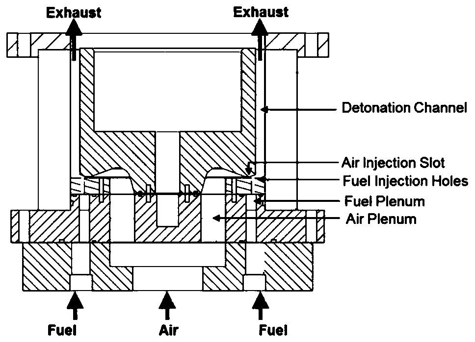
[0056] The overall design configuration of RDE is as follows Figures 4 to 5 shown.

[0057] The coaxial annulus combustor structure of RDE is a known technology.

[0058] The process of the engine providing power can be understood as: fuel is mixed with air, and after mixing, it is burned in the combustion chamber, and the combustion products are ejected through the tail nozzle to generate thrust. The focus of this invention is on fuel / air blending.

[0059] The improvement that the present invention mainly makes is:

[0060] (1) Axisymmetric surface circular seam.

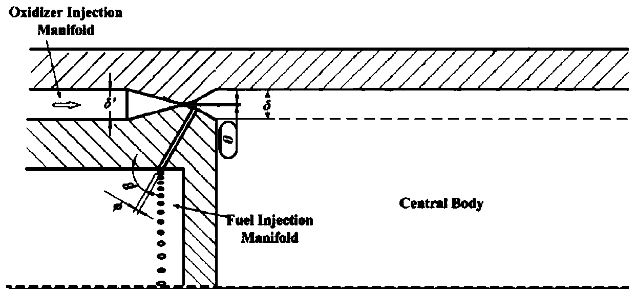
[0061] What prior art adopted is linear contraction and expansion annular seam, and the scheme of the present invention is curved surface (as Figure 5 Shown) Contraction and expans...


PUM


Abstract

The invention provides a ring cavity rotational flow opposite spraying structure based on an RDE combustion chamber. An axial symmetry hook face circular seam is adopted in a circular seam of an RDE,an included angle of the obtuse angle is formed between the transverse jet flow and the main jet flow direction of RDE, single-row annular cavity array cylindrical fuel spraying holes are evenly distributed in the inner and outer wall faces of the head of the RDE combustion chamber, and on the basis of the two-dimensional deflection, circumferential deflection is added on the fuel spraying holes.The structure has the advantages that non-linear circular seam configuration is adopted, pressure losses are reduced, and the outlet flow field is more stable. The upstream area of the transverse jetflow is decelerated, the sufficient fuel penetrating and mixing can be achieved, and the mixing efficiency is improved.

Description

technical field [0001] The invention relates to the technical field of rotary detonation engines, in particular to an annular cavity swirl counter-spray structure based on a large-scale RDE combustion chamber. Background technique [0002] The current aerospace propulsion system is mainly based on isobaric combustion rocket engines, ramjet engines and turbojet engines, etc. This kind of combustion mode often requires additional mechanical components such as booster pumps, compressors, etc. to increase the pressure of the combustible mixture ,complex structure. The detonation combustion mode has the characteristics of self-pressurization, fast combustion rate, and high thermal cycle efficiency, and is especially suitable for high-speed aerospace propulsion systems. Researchers have proposed three detonation engine concepts based on detonation combustion: oblique explosion detonation engines, pulse detonation engines, and rotary detonation engines. These three detonation eng...

Claims


Application Information

Patent Timeline
IPC IPC(8): F23R3/38
Inventor 滕宏辉郗雪辰杨鹏飞
Owner BEIJING INSTITUTE OF TECHNOLOGYGY
Learn More