Movable magnetic field arc ion plating and high-power pulse magnetron sputtering composite deposition method

A composite and high-power pulse technology of magnetron sputtering, which is applied in the field of material surface treatment, can solve the problems of high-power pulse magnetron sputtering discharge instability, limitation of deposition position and workpiece shape, low efficiency of arc plasma transmission, etc. , to achieve the effect of ensuring continuous high-density generation, improving crystal structure and stress state, and compensating for unstable discharge

Pending Publication Date: 2019-07-09
魏永强
View PDF3 Cites 0 Cited by
  • Summary
  • Abstract
  • Description
  • Claims
  • Application Information

AI Technical Summary

Problems solved by technology

[0005] The purpose of the present invention is to solve the problem of low ionization rate and thin film deposition efficiency of traditional magnetron sputtering technology, the limitation of high melting point target material use, and the current high-power pulse magnetron sputtering. The plating method uses high melting point targets, low melting point pure metals (such as aluminum, tin) or multi-element alloy materials (such as AlSi alloys) and non-metallic materials (such as graphite and semiconductor materials Si) as targets that are prone to large particle defects, bending Low efficiency of arc plasma transmission caused by magnetic filter technology, limitation of target element usage, uniform ablation of target, thin film deposition density and defects, deposition position limitation and workpiece shape limitation caused by vacuum chamber space and target source layout design, etc. The problem is to use low-melting point pure metals (such as aluminum, tin) or multi-element alloy materials (such as AlSi alloys) and non-metallic materials (such as graphite and semiconductor materials Si, etc.) as targets for high-power pulse magnetron sputtering, and reuse The arc ion plating method realizes the high melting point hard-to-ion target material to produce continuous and stable plasma with high ionization rate, and combines the magnetic field constraint of the movable coil device and the composite effect of its own bias electric field att

Method used


Image

  • Movable magnetic field arc ion plating and high-power pulse magnetron sputtering composite deposition method
  • Movable magnetic field arc ion plating and high-power pulse magnetron sputtering composite deposition method
  • Movable magnetic field arc ion plating and high-power pulse magnetron sputtering composite deposition method

Examples


specific Embodiment approach 1

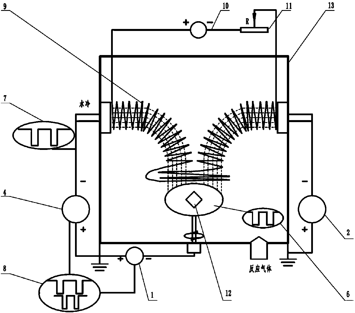
[0020] Specific implementation mode one: the following combination figure 1 , 2 and 3 illustrate the present embodiment, the active magnetic field arc ion plating and high-power pulse magnetron sputtering composite deposition method of the present embodiment uses the device including bias power supply (1), arc power supply (2), arc ion plating target source (3 ), high-power pulsed magnetron sputtering power supply (4), high-power pulsed magnetron sputtering target source (5), bias power supply waveform oscilloscope (6), high-power pulsed magnetron sputtering power supply waveform oscilloscope (7), Waveform synchronous matching device (8), movable coil device (9), movable coil device power supply (10), rheostat device (11), sample stage (12) and vacuum chamber (13);

[0021] In this device:

[0022] The substrate workpiece to be processed is placed on the sample stage (12) in the vacuum chamber (13), the arc ion plating target source (3), the high-power pulse magnetron sputte...

specific Embodiment approach 2

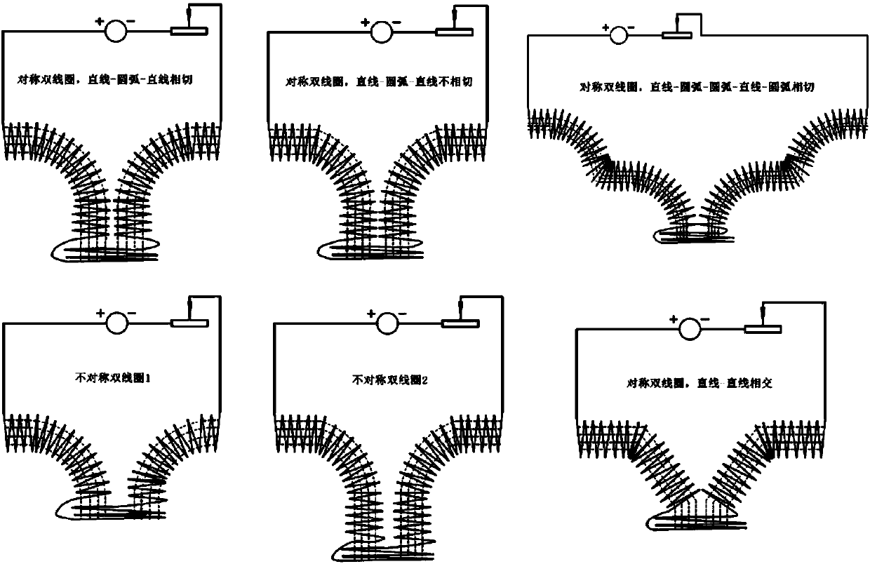
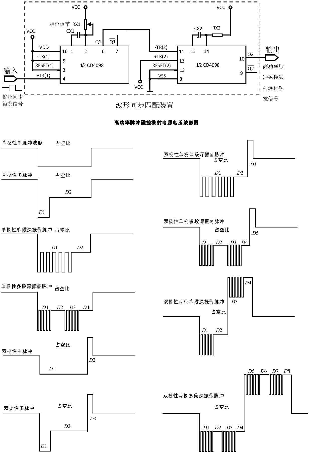
[0034] Embodiment 2: The difference between this embodiment and Embodiment 1 is that the active magnetic field arc ion plating is connected with the high-power pulse magnetron sputtering composite deposition method, the arc power supply (2) is turned on, and the movable coil device power supply (9 ) to adjust the movable coil device (9), adjust the output resistance of the rheostat device (11), and the waveform synchronous matching device (8) controls the bias power supply (1) and the high-power pulse magnetron sputtering power supply (4) to be turned on simultaneously, and the high The period of the output pulse of the power pulse magnetron sputtering power supply (4) is an integer multiple of the output pulse of the bias power supply (1), such as image 3 As shown, the pulse period output by the high-power pulsed magnetron sputtering power supply (4) is 8 times the pulse period output by the bias power supply (1), the process parameters are adjusted, and thin films are deposi...

specific Embodiment approach 3

[0035] Embodiment 3: The difference between this embodiment and Embodiment 1 is that the active magnetic field arc ion plating is connected with the high-power pulse magnetron sputtering composite deposition method, the arc power supply (2) is turned on, and the movable coil device power supply (9 ) to adjust the movable coil device (9), adjust the output resistance of the rheostat device (11), and the waveform synchronous matching device (8) controls the bias power supply (1) and the high-power pulse magnetron sputtering power supply (4) to be turned on simultaneously, and the high Power pulse magnetron sputtering power supply (4) outputs high-power pulses and bias voltage pulse waveform output by bias power supply (1) is adjustable in phase, such as image 3 As shown, when the pulse width is the same, the different phase differences make the output pulse waveforms of the two power sources completely overlap, partially overlap or not overlap, so that the reasonable matching of...


PUM


Abstract

The invention provides a movable magnetic field arc ion plating and high-power pulse magnetron sputtering composite deposition method, and belongs to the technical field of material surface treatment.The method aims at solving the problems of contamination of large particles in arc ion plating to thin films, the use limitations of target materials, losses of arc plasma in the transmitting processof a magnetic filtering device, the instability of high-power pulse magnetron sputtering and the like. A device comprises a bias power source, an arc ion plating target source, an arc ion plating target source power source, a movable coil device, a movable coil device power source, a waveform matching device, a high-power pulse magnetron sputtering target source, a high-power pulse magnetron sputtering target source power source, an oscilloscope and a vacuum chamber. The thin films are deposited, wherein the device is connected, a system is started, when the vacuum degree in the vacuum chamber is smaller than 10-4 Pa, working gas is introduced, a plating power source is switched on, the bias power source is used for adjusting energy of arc plasma, large particle defects are eliminated andtransmitting of the composite plasma is guided through the movable coil device, losses in the vacuum chamber are reduced, process parameters are set, and the thin films are prepared.

Description

technical field [0001] The invention relates to a composite deposition method of active magnetic field arc ion plating and high-power pulse magnetron sputtering, and belongs to the technical field of material surface treatment. Background technique [0002] In the process of preparing thin films by arc ion plating, due to the arc spot current density as high as 2.5~5×10 10 A / m 2 , causing molten liquid metal to appear at the arc spot position on the target surface, which is splashed out in the form of droplets under the action of local plasma pressure, and adheres to the surface of the film or is embedded in the film to form "macroparticles" (Macroparticles) Defects (BoxmanR L, Goldsmith S. Macroparticle contamination in cathodic arc coatings: generation, transport and control [J]. Surf Coat Tech, 1992, 52(1): 39-50.). In the arc plasma, since the movement speed of electrons is much greater than that of ions, the number of electrons reaching the surface of large particles ...

Claims


Application Information

Patent Timeline
IPC IPC(8): C23C14/32C23C14/35C23C14/34
CPCC23C14/325C23C14/3407C23C14/3485C23C14/35
Inventor 魏永强王好平宗晓亚张新国刘学申蒋志强
Owner 魏永强
Why Eureka
Try Eureka