Electric spark wire cutting device and liquid amount control method between electrodes

An EDM wire and cutting device technology, applied in electrode manufacturing, manufacturing tools, electric processing equipment, etc., can solve problems such as affecting processing quality, easy bifurcation of working fluid, and precise control of working fluid between electrodes.

Active Publication Date: 2019-07-12
SICHUAN UNIVERSITY OF SCIENCE AND ENGINEERING
View PDF13 Cites 3 Cited by
  • Summary
  • Abstract
  • Description
  • Claims
  • Application Information

AI Technical Summary

Problems solved by technology

The pouring type is to pour the working fluid sideways on the discharge area of ​​the workpiece. The nozzle and the electrode wire are not in the same axis, and there is a certain angle, which cannot form a water column. The pouring type is easy to impact the electrode wire, which seriously affects the finishing quality of multiple cutting.
The coaxial normal pressure liquid spray type is to spray liquid up and down, the nozzle is coaxial with the electrode wire, although the coaxial normal pressure liquid spray type reduces the disturbance of the electrode wire and improves the cooling state between the electrodes, but there are six small spray holes in the nozzle The injected working fluid is prone to bifurcation, and the working fluid splashed on the surface of the workpiece will disturb the electrode wire, making it difficult to form a water column. Neither the pouring type nor the liquid spraying type can accurately control the amount of working fluid entering the discharge gap.
The cur

Method used


Image

  • Electric spark wire cutting device and liquid amount control method between electrodes
  • Electric spark wire cutting device and liquid amount control method between electrodes

Examples


Embodiment 1

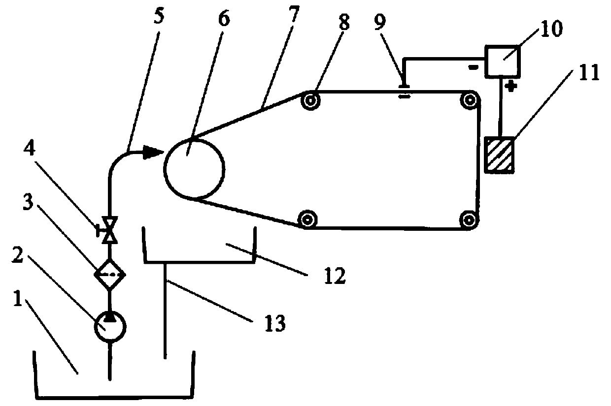
[0021] Such as figure 1 It is a schematic structural diagram of a wire EDM device under an embodiment of the present invention. It is mainly composed of two parts: a liquid supply system and a cutting system. As shown in the figure, the cutting system includes 6 wire barrels and 4 guide wheels at different positions. 8. The electrode wire 7 and the pulse power supply 10 connected to the electrode wire 7, the workpiece 11 is cut at the position shown in the figure, and the position of the workpiece can be adjusted according to the actual situation. The electrode wire is driven by the wire barrel and is in the four guide rails 8 The outside rotates to cut the workpiece through the wire electrode at the workpiece 11, and the rotation speed of the wire electrode can be adjusted by the rotation speed of the wire barrel 6 to control the rotation speed of the wire electrode through the wire barrel 6.

[0022] Such as figure 1 As shown, the left position of the figure is a schematic dia...

Embodiment 2

[0035] Embodiment 2: This embodiment discloses a working medium for electric spark cutting, that is, an inter-electrode working fluid, which is used for electric spark cutting in embodiment 1. The working medium is a SiC nanofluid working medium. The nanofluid can form uniform and stable negatively charged micelles, and the repulsive force between the negatively charged micelles prevents their coalescence. Therefore, the working medium does not require external stirring to maintain long-term uniformity, and it can cut the surface of the workpiece while cutting online. Modification does not require post-processing operations on the workpiece.

[0036] The composition and mass percentage of SiC nanofluid are as follows

[0037] 98 parts of deionized water;

[0038] 0.8 parts of SiC nanoparticles with a particle size of 50nm;

[0039] Dispersion stabilizer 0.6 part of sodium carboxymethyl cellulose;

[0040] Surfactant 1.2 parts of sodium dodecylbenzene sulfonate;

[0041] 0.4 parts of an...


PUM

PropertyMeasurementUnit
Thicknessaaaaaaaaaa
Thicknessaaaaaaaaaa

Abstract

The invention discloses an electric spark wire cutting device. The electric spark wire cutting device comprises a liquid supply system and a cutting system, wherein the liquid supply system is used for providing an inter-electrode working solution, and the cutting system is used for machining a workpiece by using an electric discharge wire; the cutting system comprises a lead barrel, a plurality of guide wheels and an electrode wire, wherein the electrode wire winds the wire barrel and the guide wheel and can be driven by the wire barrel to move between the guide wheel and a discharging gap; and the liquid supply system comprises a nozzle capable of spraying the working solution, and the nozzle sprays the working solution on the electrode wire of the wire barrel, so that the electrode wireis wrapped with the working solution, and the working liquid amount between the electrodes can be controlled by controlling the wire speed of the electrode wire; and the wire barrel drives the electrode wire to enter the electrode wire wrapped with the working solution into the discharging gap.

Description

Technical field [0001] The invention relates to the field of electric spark cutting. Background technique [0002] Wire EDM is the use of electrode wire to perform pulse discharge corrosion processing on the workpiece. When the voltage between the electrodes is greater than the breakdown voltage, the liquid medium between the electrodes is ionized to form a discharge channel, and the material near the discharge point is melted and vaporized at a high temperature instantaneously. Under the combined action of the force and the electrode wire, the electro-erosion products are taken out of the workpiece, forming overlapping electro-erosion pits. Through experiments and thermal conduction analysis, Dibitino et al. concluded that only about 18% and 8% of the energy allocated to the workpiece and electrodes, 74% of the energy is absorbed by the working fluid, and the energy loss is large. He Ciwen and others studied the mechanism of working fluid and emphasized that the amount of fluid...

Claims


Application Information

Patent Timeline
IPC IPC(8): B23H7/36B23H7/02B23H7/10
CPCB23H7/02B23H7/105B23H7/36
Inventor 郭翠霞吴张永刘康胡光忠杨大志李秀兰周军超王瑞张宏志
Owner SICHUAN UNIVERSITY OF SCIENCE AND ENGINEERING
Why Eureka
Try Eureka