Additive and subtractive compound manufacturing equipment

A technology for manufacturing equipment and adding and subtracting materials, applied in the field of 3D printing, can solve the problems of unprintable substrate temperature control, increase the cost of tool use, and affect the service life of the tool, and achieve diversification of printing methods, prolong service life, and reduce long-term use. cost effect

Pending Publication Date: 2019-07-19
BEIJING WANWEI ADDITIVE MFG TECH CO LTD
View PDF0 Cites 7 Cited by
  • Summary
  • Abstract
  • Description
  • Claims
  • Application Information

AI Technical Summary

Problems solved by technology

[0004] 1. At present, most of the equipment for adding and subtracting materials use the tool switching device on the machining center to switch between the subtractive tool and the additive forming component. This method greatly reduces the production efficiency
[0005] 2. Cooling of cutting tool: At present, the processing is basically dry milling, without cooling treatment for the tool, dry processing will affect the service life of the tool and increase the cost of tool use;
[0006] 3. For the cooling of the work surface, the existing method is to add heat insulators between the work surface and the printing substrate support, but this method cannot regulate the temperature of the printing substrate, and the cooling effect is poor

Method used


Image

  • Additive and subtractive compound manufacturing equipment
  • Additive and subtractive compound manufacturing equipment
  • Additive and subtractive compound manufacturing equipment

Examples


Embodiment 1

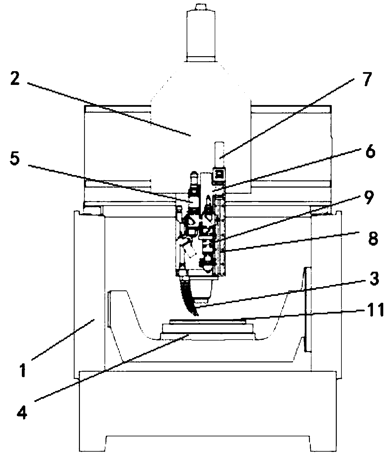
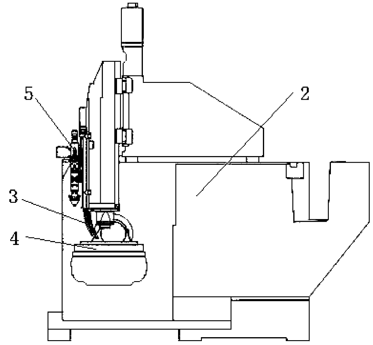
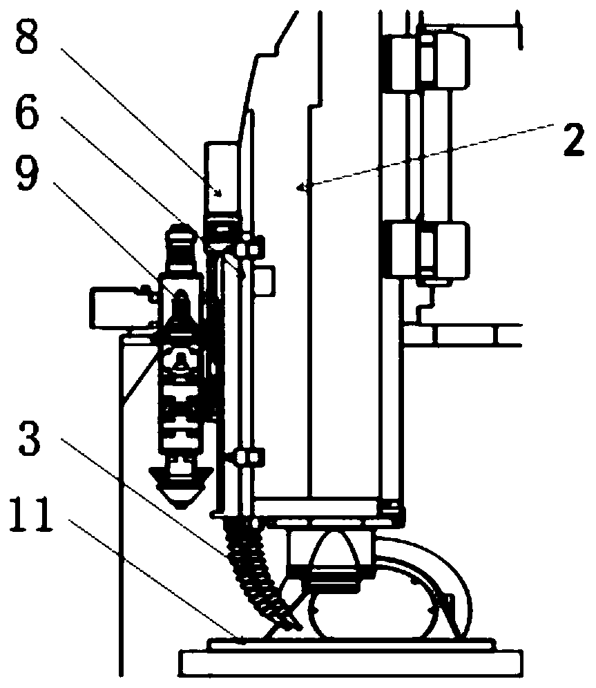
[0040] see Figure 1-3 As shown, the equipment includes a machining center 1, an additive forming component 5 and a cooling nozzle 3;

[0041] The additive forming component 5 includes a connecting plate 6, a motor 7, a linear motion linear module 8 and an energy deposition metal additive forming device (a laser cladding head 9 is used in this embodiment);

[0042] The linear motion linear module 8 is fixed on the spindle box 2 of the machining center 1, and the linear motion linear module 8 is slidably connected to the connection plate 6; the laser cladding head 9 is fixedly installed on the connection plate 6; the motor 7 moves to the linear motion linear module 8 provides power so that the connecting plate drives the laser cladding head 9 to move up and down; the purpose of this design is to separate the up and down movement of the laser cladding head 9 from the up and down movement of the main shaft. The upper linear motion linear module 8 lowers the laser cladding head 9...

Embodiment 2

[0050] In order to quickly adjust the atmosphere environment in the process of adding and subtracting materials in real time, avoid the influence on the atmosphere in the process of adding and subtracting materials, and effectively ensure the processing quality of parts, the invention also provides an increasing Subtractive composite manufacturing equipment.

[0051] Such as Figure 6 As shown, the atmosphere regulating cycle device includes a first sealed box 16, a second sealed box 17, an inert gas source 18 and a purification unit 19;

[0052] The first sealed box 16 communicates with the second sealed box 17 through a first pipeline 20 and a second pipeline 21;

[0053] The first sealed box 16 and the second sealed box 17 need to be designed in an environment close to anhydrous and oxygen-free according to the characteristics of different materials in the printing process, and can directly print various metal materials such as titanium alloys, avoiding water in the printi...


PUM


Abstract

The invention relates to additive and subtractive compound manufacturing equipment. In the equipment, additive and subtractive processes are finished independently, and a subtractive tool and an additive forming assembly are not switched by using a tool switching device on a machining center, so that the production efficiency is improved greatly. The equipment comprises the machining center, the additive forming assembly and a cooling nozzle. The additive forming assembly comprises a connecting plate, a motor, a rectilinear motion linear module and an energy depositing metal additive forming device. The rectilinear motion linear module is fixed to a spindle box of the machining center and is slidably connected to the connecting plate. The energy depositing metal additive forming device isfixedly mounted on the connecting plate. The motor provides power to the rectilinear motion linear module, so that the connecting plate drives the energy depositing metal additive forming device to move up and down. The cooling nozzle is fixed to the spindle box of the machining center, and an air outlet faces a working table-board of the machining center.

Description

technical field [0001] The invention belongs to the technical field of 3D printing, and in particular relates to a compound manufacturing equipment of adding and subtracting materials. Background technique [0002] Additive manufacturing technology is to form a three-dimensional entity through the orderly accumulation or accumulation of materials. Because of its high material utilization rate and the advantages of integrated forming of complex parts, additive manufacturing technology, especially metal additive manufacturing technology, has entered the It has reached the industrial application stage in the fields of aerospace, nuclear energy, marine engineering, automotive engineering and so on. [0003] However, there are still the following problems for the existing equipment for adding and subtracting materials: [0004] 1. At present, most of the equipment for adding and subtracting materials use the tool switching device on the machining center to switch between the sub...

Claims


Application Information

Patent Timeline
Patent Type & Authority Applications(China)
IPC IPC(8): B23P23/04B23Q11/12B23Q1/01B23K9/167B23K9/173B22F3/105B22F3/24B33Y30/00
CPCB23P23/04B23Q11/12B23Q1/012B23K9/167B23K9/173B22F3/24B33Y30/00B22F2003/247B22F10/00B22F12/90B22F10/32B22F12/70B22F10/25B22F12/82B22F12/222B22F12/20Y02P10/25
Inventor 薛飞周宇飞卢秉恒王俊岭郭兴安
Owner BEIJING WANWEI ADDITIVE MFG TECH CO LTD
Why Eureka
Try Eureka