Power module of SIC electric automobile

A technology of power modules and electric vehicles, which is applied in the direction of electric vehicles, power electronics modification, output power conversion devices, etc., can solve problems such as low reliability, low power density, and reduced working life, so as to reduce the industry application threshold , The effect of small insulation gap between components and large power density ratio

Pending Publication Date: 2019-07-19
SHENZHEN HOVERBIRD ELECTRONICS TECH CO LTD
View PDF0 Cites 3 Cited by
  • Summary
  • Abstract
  • Description
  • Claims
  • Application Information

AI Technical Summary

Problems solved by technology

There is an installation layout type of independent capacitors. Due to the large internal fastener installation gap, component insulation gap, and component layout gap, the controller is large in size, heavy in weight, and relatively low in power density.
Due to the structural limitation of existing independent capacitors and IGBT layout connections, it is difficult to further reduce and optimize the stray inductance of the main circuit, which is limited in the application of new power devices with faster switching speeds
There are independent capacitors, and the heat dissipation performance is limited when the working environment temperature is high. The heat can only rely on radiation heat dissipation, and the working life is reduced.
[0004] The existing automobile controller housing uses an aluminum shell structure, which has poor sealing performance, poor equipment stability, low reliability, and short life
Due to the decentralized organization of the controller, it is very difficult for various car manufacturers to research and apply the technology. They usually purchase from professional manufacturers, and the application method is not flexible enough. The adjustment of the motor performance can only be completed by coordinating professional manufacturers.

Method used


Image

  • Power module of SIC electric automobile
  • Power module of SIC electric automobile
  • Power module of SIC electric automobile

Examples


Embodiment Construction

[0027] The following will clearly and completely describe the technical solutions in the embodiments of the present invention with reference to the accompanying drawings in the embodiments of the present invention. Obviously, the described embodiments are only some, not all, embodiments of the present invention. Based on the embodiments of the present invention, all other embodiments obtained by persons of ordinary skill in the art without creative efforts fall within the protection scope of the present invention.

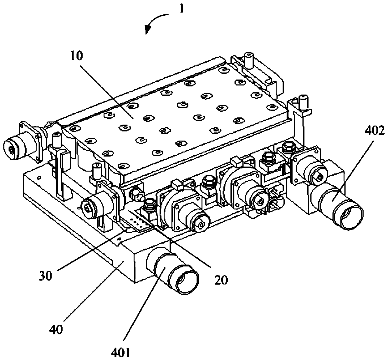
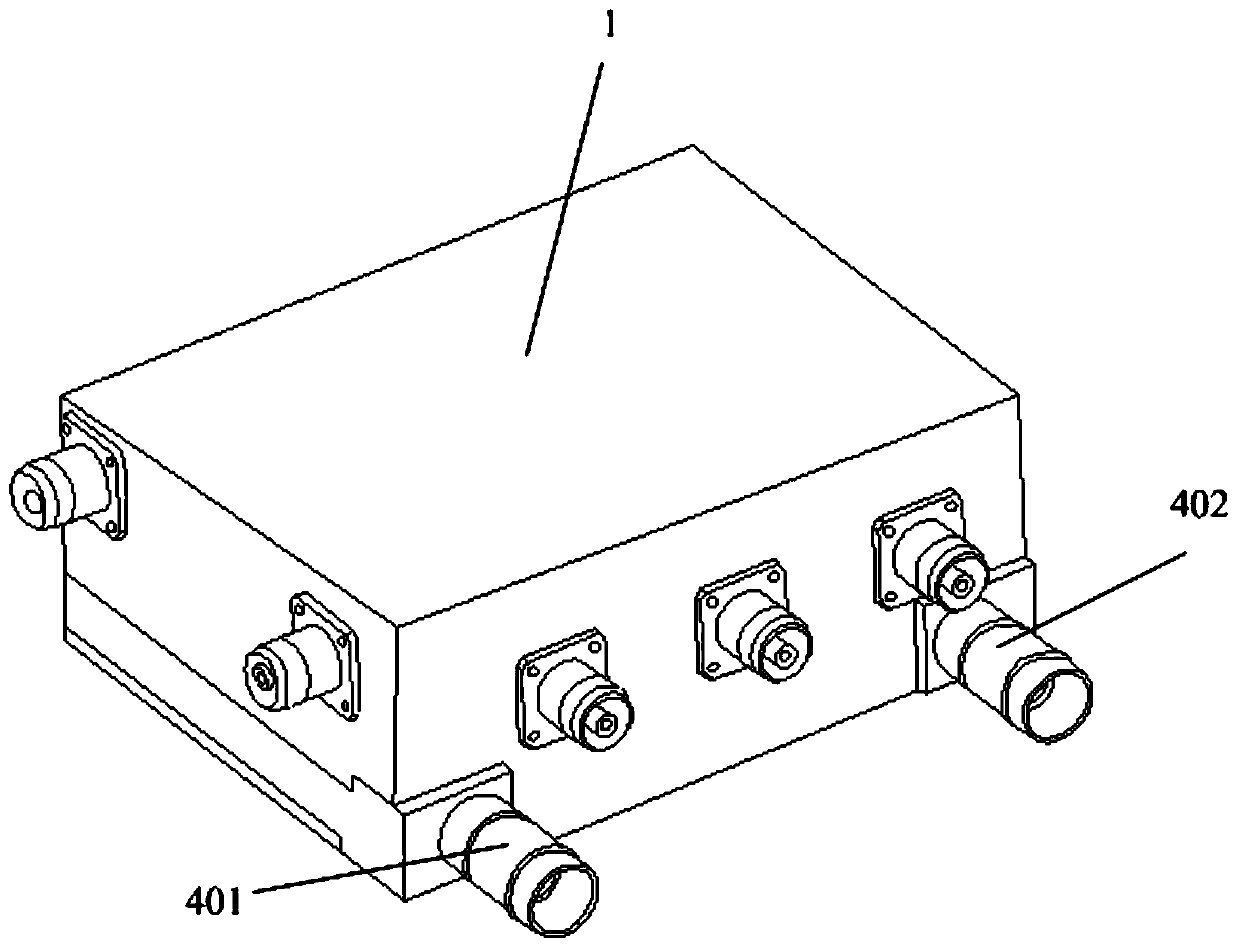
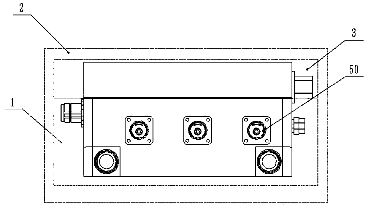
[0028] see figure 1 , figure 2 , image 3 , Figure 4 and Figure 5 , Embodiment, a power module 1 of a SIC electric vehicle, including: SICMOSFET device 30, radiator 40, capacitor core group 10, driver 20, electrical terminal 50, water inlet 401, water outlet 402 and so on. The components of the power module 1 described above are integrally encapsulated and filled by a three-layer potting technique of epoxy resin, and there is no metal casing. Functionally d...


PUM


Abstract

The invention provides a power module of a SIC electric automobile. The power module comprises a SIC MOSFET device, a radiator, a low-inductance busbar, a capacitor core group, a driver, a sensor anda hydroelectric terminal; the power module is sequentially provided with the radiator, the SIC MOSFET device, the driver and the capacitor core group from bottom to top; the capacitor core group is electrically connected with the SIC MOSFET device and is arranged above the SIC MOSFET device; the driver is installed and fixed on an auxiliary terminal of the SIC MOSFET device through welding; and each component of the power module is formed by integrally packaging and filling through an epoxy resin three-layer filling and sealing technology, and a metal shell is not needed. According to the power module, a motor control unit (MCU) is detached and separated, and the motor control unit and the power module can be installed together to serve as a complete automobile controller according to therequirements of a vehicle factory in an application, and the function of the motor control unit can be integrated into a vehicle control unit (VCU) by the vehicle factory and the power module is onlyused as an execution part for use by the vehicle factory.

Description

technical field [0001] The invention relates to the field of electric vehicle controllers, in particular to a power module of a SIC electric vehicle. Background technique [0002] The power module is an independent functional body that integrates the necessary components in a certain combination to meet the work of power semiconductor devices. The internal components of this module are connected by fasteners or soldered, and the external shell can be made of aluminum. The alloy casing can also be potted as a whole without using the casing. In the prior art, power modules mainly appear in megawatt-level high-power converter devices, and power semiconductor devices are mainly IGBTs, while the existing products in the electric vehicle industry are power controllers, namely power modules. and motor control unit (MCU), and the semiconductor device is also an IGBT. [0003] The layout methods in the existing automotive controllers are mainly: independent capacitors, IGBT split l...

Claims


Application Information

Patent Timeline
IPC IPC(8): H02M1/00H05K7/20H01L23/367H01L23/467H01L23/473B60L15/20B60L3/00
CPCH02M1/00H05K7/2089H05K7/20909H05K7/20927H01L23/367H01L23/467H01L23/473B60L15/20B60L3/00Y02T10/72
Inventor 刘斌杨光杜野马伯乐黄小华王田军
Owner SHENZHEN HOVERBIRD ELECTRONICS TECH CO LTD
Why Eureka
Try Eureka