Supercharge Your Innovation With Domain-Expert AI Agents!

Direct thermal injection thermal analysis

A technology of thermal analysis and electromagnetic radiation, applied in the field of thermal analysis, can solve the problems of slow heating and cooling of the instrument, achieve the effect of increasing the sample temperature and reducing the cost of the instrument

Active Publication Date: 2019-07-19
TA INSTR WATERS
View PDF12 Cites 0 Cited by
  • Summary
  • Abstract
  • Description
  • Claims
  • Application Information

AI Technical Summary

Problems solved by technology

Traditional instruments heat and cool slowly, require a lot of energy to vary sample temperature, and require regular routine maintenance and replacement

Method used


Image

  • Direct thermal injection thermal analysis
  • Direct thermal injection thermal analysis
  • Direct thermal injection thermal analysis

Examples


Embodiment 1

[0064] Example 1 - Thermogravimetric analyzer with direct thermal injection.

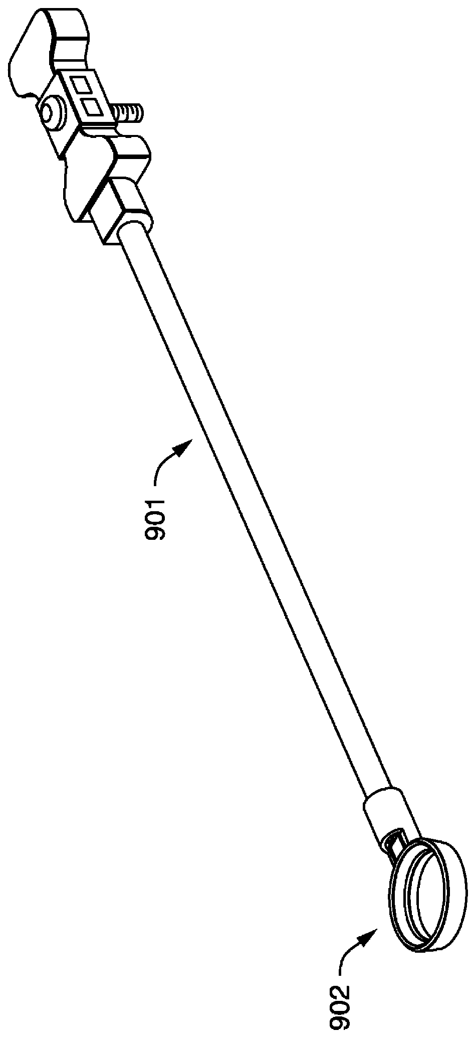
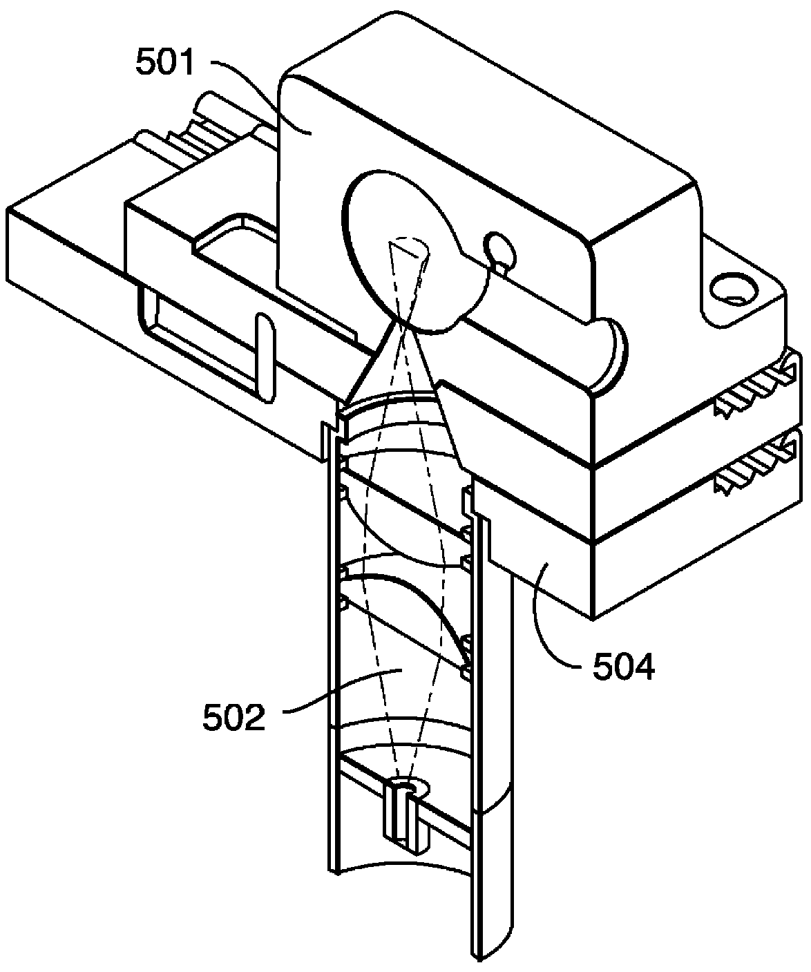
[0065] The instrumentation employed a balance and part of the electronics from a Q600 (SDT) from TA Instruments. Components mate with an off-the-shelf diode laser system (DILAS MINI 808nm) custom designed cavity and off-the-shelf control electronics. The instrument is fitted with a closed chamber made of brass. Cavity dimensions similar to Figure 2B Dimensions shown and described in. The upper radius is 0.5625 inches. The lower radius is 0.5 inches. The cavity includes a cylindrical portion with a height of about 0.25 inches and a radius of about 0.5 inches. The interior surfaces of the cavity are coated with gold to provide a reflective surface.

[0066] Diode lasers generate electromagnetic radiation with a wavelength of 808nm. The power of the laser to heat the sample was about 50W. The laser was equipped with an optical fiber (DILAS, MINI, 400um core, 2m long fiber) to transmit the li...


PUM

PropertyMeasurementUnit
wavelengthaaaaaaaaaa
radiusaaaaaaaaaa
wavelengthaaaaaaaaaa

Abstract

The present disclosure relates generally to thermal analyses having direct application of thermal energy to a sample.

Description

[0001] related application [0002] This application claims the benefit of U.S. Provisional Patent Application Serial No. 62 / 425,169, entitled "DirectThermal Injection Thermal Analysis," filed November 22, 2016, the contents of which are incorporated by reference in their entirety This article. technical field [0003] The present disclosure generally relates to thermal analysis, which applies thermal energy directly to a sample in the form of electromagnetic radiation (eg, light). Background technique [0004] The field of thermal analysis is the branch of materials science in which the properties of materials are studied as a function of temperature. Two of the more common thermal analysis methods are thermogravimetric analysis (TGA) and differential scanning calorimetry (DSC). TGA measures the amount and rate of change in mass of a sample based on temperature and time in a controlled atmosphere. DSC measures the difference in the amount of heat required to increase the...

Claims


Application Information

Patent Timeline
Patent Type & Authority Applications(China)
IPC IPC(8): G01N25/48G01N5/04
CPCG01N25/4806G01N25/4813G01N25/4846G01N25/4866G01N5/04G01N1/44G01K7/02G01N25/20
Inventor P.帕尔默S.阿波斯托勒斯库K.E.德拉加诺维奇D.J.马恩肯V.帕里赫
Owner TA INSTR WATERS
Features
  • R&D
  • Intellectual Property
  • Life Sciences
  • Materials
  • Tech Scout
  • Unparalleled Data Quality
  • Higher Quality Content
  • 60% Fewer Hallucinations
Learn More