Device and method for non-contact measurement and non-contact control over vibration of flexible cantilever beam

A flexible cantilever, non-contact technology, used in measuring devices, non-electric variable control, mechanical oscillation control and other directions, can solve the problems of high cost, can only measure the displacement of a certain point on the object, and difficult to operate. wide range of effects

Inactive Publication Date: 2019-08-09
ANHUI UNIV OF SCI & TECH
View PDF7 Cites 1 Cited by
  • Summary
  • Abstract
  • Description
  • Claims
  • Application Information

AI Technical Summary

Problems solved by technology

; The accelerometer sensor and the angular rate gyro sensor are sensitive to noise, and there are problems such as hysteresis and temperature drift that affect their accuracy, and they can only measure the displacement of a certain point on the object. An accelerometer or an angular rate gyroscope; the measurement range of the photoelectric position sensor is small, the structure is complex, the operation is difficult, the calculation process is cumbersome and the cost is expensive; due to factors such as its own strength, fatigue life and temperature resistance, piezoelectric materials are widely used in applications. subject to certain restrictions

Method used


Image

  • Device and method for non-contact measurement and non-contact control over vibration of flexible cantilever beam

Examples


Embodiment Construction

[0015] The present invention will be further explained below through specific embodiments and accompanying drawings, but the embodiments of the present invention are not limited thereto.

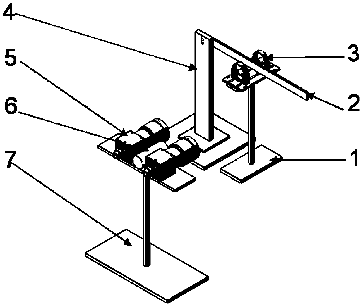
[0016] Such as figure 1 As shown, a device for non-contact vibration measurement and non-contact control of a flexible cantilever beam includes a cantilever beam 1, one end of the flexible cantilever beam 2 is fixed by a cantilever beam bracket 4, called a fixed end, and the other end is a free The electromagnetic coil 2 is symmetrically located on both sides of the flexible cantilever beam 2, and the electromagnetic coil is fixed by the coil bracket 1. The binocular CCD camera 5 is composed of two industrial cameras, which are located at the same level as the flexible cantilever beam 2. The optical axis of the eye CCD camera 5 is perpendicular to the flexible cantilever beam 2, the laser pointer 6 is located between the binocular CCD cameras, and the laser pointer 6 and the binocular camera...


PUM


Abstract

The invention relates to a device and method for non-contact measurement and non-contact control over vibration of a flexible cantilever beam. The device comprises the flexible cantilever beam, a cantilever beam bracket, binocular CCD cameras, a camera bracket, a laser pen, electromagnetic coils, a PC and an electromagnetic controller. The device is characterized in that one end of the flexible cantilever beam is fixed through the cantilever beam bracket and is called a fixed end, and the other end of the flexible cantilever beam is a free end; the binocular CCD cameras are arranged in front of the flexible cantilever beam, and the two cameras are horizontally and parallelly arranged; the binocular CCD cameras collect images of mark points of the laser pen, acquire an image sequence of bending and torsional vibration information of the flexible cantilever beam, and transmits the images to the PC through a data line; the electromagnetic coils are symmetrically arranged on the two sidesof the flexible cantilever beam and keep the same horizontal height as the flexible cantilever beam; and the PC processes the collected vibration image sequence, sends vibration control information tothe electromagnetic controller, controls the magnetism of an electromagnet, and realizes vibration control over the flexible cantilever beam. The device and method can realize non-contact measurementand control without being in contact with or changing the vibration characteristics of a measured object, and can be widely applied and studied.

Description

technical field [0001] The invention relates to the field of non-contact measurement and non-contact vibration control of a large space flexible cantilever beam structure, in particular to a device and method for non-contact measurement and non-contact vibration control of a flexible cantilever beam. Background technique [0002] With the rapid development of aerospace technology, large-scale flexible cantilever beam structures are widely used in space stations, satellites and other spacecraft. Due to their light weight, large-scale flexible cantilever beam structures can increase the payload of spacecraft; lower stiffness can reduce machining Difficulty, it can also reduce the volume of the execution workpiece and improve the execution efficiency of the execution workpiece. However, due to the low stiffness and small structural damping of the large flexible cantilever beam structure, when it is stimulated by the outside, the structure will flutter, and eventually even lead ...

Claims


Application Information

Patent Timeline
Patent Type & Authority Applications(China)
IPC IPC(8): G01H9/00G05D19/02
CPCG01H9/00G05D19/02
Inventor 高飞彪马天兵陈南南
Owner ANHUI UNIV OF SCI & TECH
Why Eureka
Try Eureka