Fiber grating directional pressure sensor, fiber grating preparation method and device
A technology of pressure sensor and optical fiber grating, which is applied in the direction of fluid pressure measurement, cladding optical fiber, and measuring device using optical methods, which can solve the problems of low sensitivity of pressure sensor, cumbersome and complicated manufacturing process, and non-directional pressure sensor Achieve the effects of reducing production difficulty, improving sensitivity, and reducing writing difficulty
- Summary
- Abstract
- Description
- Claims
- Application Information
AI Technical Summary
Problems solved by technology
Method used
Image

Examples
Embodiment 1
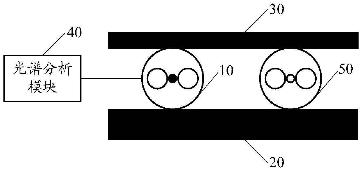
[0055] Such as figure 1 As shown, the embodiment of the present invention provides a fiber grating directional pressure sensor 100 , which includes a double-hole optical fiber 10 , a bearing plate 20 , a force plate 30 and a spectrum analysis module 40 .
[0056]In the embodiment of the present invention, the connection relationship of each part of the fiber grating directional pressure sensor is as follows:
[0057] The double-sided hole optical fiber 10 is placed between the load-bearing plate 20 and the force plate 30, and the double-sided hole optical fiber 10 and the force plate 30 are placed on the load-bearing plate 20, then the external force to be measured is applied to the force plate 30, and the double-sided hole The output end of the optical fiber 10 is connected with the spectral analysis module 40, and the light beam input by the double-hole optical fiber 10 is output to the spectral analysis module 40. During measurement, the refraction of the light beam in the ...
Embodiment 2
[0073] Such as Figure 4 As shown, the embodiment of the present invention provides a fiber grating preparation method, which is applied to the preparation of fiber grating directional pressure sensors, including but not limited to the following steps:
[0074] S101. Build a raster writing system.
[0075] In the above step S101, the grating writing system utilizes the characteristics of the change in the refractive index of the optical fiber core, and uses a special process, such as thermal processing of ultraviolet light, to make the refractive index of the optical fiber core undergo a permanent periodic change to form a specific grating; the characteristics of the grating Similar to the wavelength selector, it can reflect the incident light whose wavelength meets the Bragg reflection condition.
[0076] In the embodiment of the present invention, the grating writing system is used to write a Bragg grating, and its central wavelength satisfies: λB=2neffΛ, where 2neff is the...
Embodiment 3
[0094] The embodiment of the present invention provides a fiber grating preparation device 200, which is applied to the preparation of fiber grating directional pressure sensors, including a high temperature and high pressure reactor 201, a charge-coupled device image sensor CCD202, an ultraviolet laser 203, a light source 204, and a lens group 205 , a phase mask 206 , an electric rotating fixture 207 , a three-dimensional adjustment frame 208 , a PC module 209 and a transmitted light analysis module 210 .
[0095] The fiber grating preparation device 200 provided in the embodiment of the present invention is used to prepare a Bragg grating in a double-hole fiber. The fiber grating preparation method is used to prepare the fiber grating directional pressure sensor.
[0096] Such as Figure 7 As shown, the connection relationship of each part of the above-mentioned fiber grating preparation device is as follows:
[0097]The ultraviolet laser 203, the lens group 205 and the ph...
PUM
| Property | Measurement | Unit |
|---|---|---|
| length | aaaaa | aaaaa |
Abstract
Description
Claims
Application Information
 - R&D
- Intellectual Property
- Life Sciences
- Materials
- Tech Scout
- Unparalleled Data Quality
- Higher Quality Content
- 60% Fewer Hallucinations
Browse by: Latest US Patents, China's latest patents, Technical Efficacy Thesaurus, Application Domain, Technology Topic, Popular Technical Reports.
© 2025 PatSnap. All rights reserved.Legal|Privacy policy|Modern Slavery Act Transparency Statement|Sitemap|About US| Contact US: help@patsnap.com