Method for manufacturing multi-core long-period fiber gratings and fiber rotation positioning device

A multi-core optical fiber and fiber grating technology, applied in cladding optical fiber, optical waveguide and light guide, etc., can solve the problems that it is difficult to meet the production requirements of batch production and multi-grating period, and the variation of core refractive index is not uniform, so as to achieve the goal of production The process is easy to control, the quality of writing is improved, and the effect of simple implementation

Inactive Publication Date: 2012-02-01
HARBIN ENG UNIV
View PDF2 Cites 2 Cited by
  • Summary
  • Abstract
  • Description
  • Claims
  • Application Information

AI Technical Summary

Problems solved by technology

[0003] The realization of the formation mechanism and manufacturing technology of LPFG has been gradually improved, but most of them are limited to the research of single-core LPFG, or the fabrication of FBG in multi-core fibers [US Patent No. 20070286561A1 and NO.20070201793A1], most of these fiber gratings are produced by single-side exposure and one-time writing, and the refractive index of multiple cores varies unevenly, which is difficult to meet the requirements of batch production and multi-grating period production

Method used


Image

  • Method for manufacturing multi-core long-period fiber gratings and fiber rotation positioning device
  • Method for manufacturing multi-core long-period fiber gratings and fiber rotation positioning device
  • Method for manufacturing multi-core long-period fiber gratings and fiber rotation positioning device

Examples


Embodiment approach 1

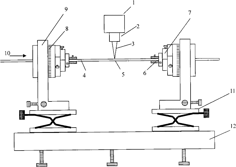
[0026] First calibrate the high frequency CO 2 Laser, and determine the parameters of the laser, such as operating frequency, duty cycle and release time, etc. The laser energy at the fiber exposure point 5 can be changed by adjusting parameters such as the frequency of the laser pulse and the Q release time. Secondly, design the resonant wavelength and loss peak size of the multi-core long-period fiber grating according to the actual production requirements, and determine the period and length of the grating.

[0027] Taking the fabrication of a four-core fiber long-period fiber grating as an example, the following steps are included:

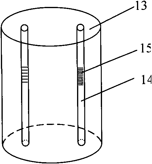
[0028] 1) Take a multi-core optical fiber 4, the optical fiber has four cores 14, and the four cores are symmetrically distributed on concentric circles, one section of which is stripped of the coating layer, which is about 50mm; use non-woven cloth dipped in alcohol and Diethyl ether mixture, repeatedly wipe the outer cladding 13 of the opt...

Embodiment approach 2

[0035] First calibrate the high frequency CO 2 Laser, and determine the parameters of the laser, such as operating frequency, duty cycle and release time, etc. The laser energy at the fiber exposure point 5 can be changed by adjusting parameters such as the frequency of the laser pulse and the Q release time. Secondly, design the resonant wavelength and loss peak size of the multi-core long-period fiber grating according to the actual production requirements, and determine the period and length of the grating.

[0036] Taking the fabrication of double-period dual-core fiber long-period fiber grating as an example, the following steps are included:

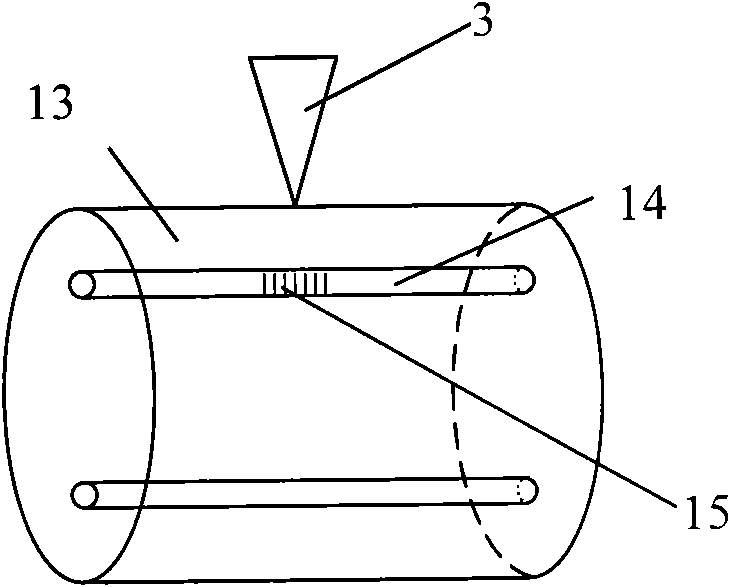
[0037] 1) Get a multi-core optical fiber 4, the optical fiber has two cores 14, such as figure 2 As shown, one section of the coating layer is stripped, which is about 50 mm; use a non-woven cloth dipped in a mixture of alcohol and ether, repeatedly wipe the outer cladding 13 of the optical fiber, and fix it on the optical fiber...


PUM


Abstract

The invention provides a method for manufacturing multi-core long-period fiber gratings and a fiber rotation positioning device. The method comprises the following steps of: (1) installing a multi-core fiber which has multiple fiber cores on different planes on the fiber rotation positioning device, wherein a CO2 laser pulse is arranged above the fiber rotation positioning device; (2) adjusting the fiber rotation positioning device so that one fiber core in the multi-core fiber is aligned with the CO2 laser pulse, and carrying out multiple exposure to make a grating on the fiber core; (3) andrepeating step (2), and respectively writing gratings into other fiber cores of the multi-core fiber. The invention is convenient to implement, greatly enhances the grating writing quality, enables the manufacturing process to be controlled easily, reduces the multi-core grating writing difficulty, and is suitable for large-scale production. Multiple fiber gratings are integrated into one fiber, thereby enhancing the integration of optical devices in the fiber; and multiple physical quantities can be simultaneously measured.

Description

technical field [0001] The invention belongs to the technical fields of optical fiber communication and optical fiber sensing, and relates to a manufacturing technology of a multi-core long-period optical fiber grating. Background technique [0002] A typical optical fiber is a single-core structure, and the cladding surrounds the core to form a cylindrical optical waveguide. A multi-core optical fiber contains multiple cores in the same outer cladding, and each core is surrounded by a cladding material. Therefore, each fiber core is an optical (fiber) waveguide, that is, multiple single-core fibers are integrated in a multi-core fiber. The concept of multi-core optical fiber was proposed as early as the end of the 1970s. The purpose is to simultaneously solve the two major problems of reducing the manufacturing cost of optical fiber cables and developing high-density and large-core optical cables. However, it was not until the 1990s that with the continuous development an...

Claims


Application Information

Patent Timeline
Patent Type & Authority Patents(China)
IPC IPC(8): G02B6/02
Inventor 苑立波王雪关春颖
Owner HARBIN ENG UNIV
Why Eureka
Try Eureka