3D printing integrated radiator and application thereof in phased-array antenna

A technology for radiators and heat exchange containers, applied to antennas, antenna arrays, antenna parts, etc., can solve the problem of uneven heat exchange of heat exchange devices, large heat exchange dead volume of heat exchange containers, and no heat exchange uniformity effect and other problems, to achieve the effect of large number of partitions, small spacing, and pressure pulsation suppression

Inactive Publication Date: 2019-08-23
UNIV OF ELECTRONICS SCI & TECH OF CHINA
View PDF23 Cites 13 Cited by
  • Summary
  • Abstract
  • Description
  • Claims
  • Application Information

AI Technical Summary

Problems solved by technology

This patent uses the raised part to form a water channel for water cooling and heat exchange, but it does not consider that the flow rate of the heat exchange fluid at the inlet is large, and the pressure drop increases, which reduces the flow rate of the heat exchange fluid in the subsequent process, and the heat exchange fluid with reduced flow rate It cannot fully contact with the inside of the heat exchange container, resulting in a large "heat exchange dead volume" inside the heat exchange container. At the same time, the temperature of the heat exchange fluid rises in the second half of the fluid stroke. In the case of "thermal dead volume", the heat exchange of the whole heat exchange device is extremely uneven, without any heat exchange uniformity effect
[0008] CN200820115950.9 discloses an aluminum pass-through water-cooling heat sink. The water-cooling heat sink is processed with continuously bent waterways inside and is provided with corresponding water inlets and water outlets. As in the above reference document, only water cooling is considered. Heat transfer, without considering the uniform temperature performance of heat transfer

Method used


Image

  • 3D printing integrated radiator and application thereof in phased-array antenna
  • 3D printing integrated radiator and application thereof in phased-array antenna
  • 3D printing integrated radiator and application thereof in phased-array antenna

Examples


Embodiment 1

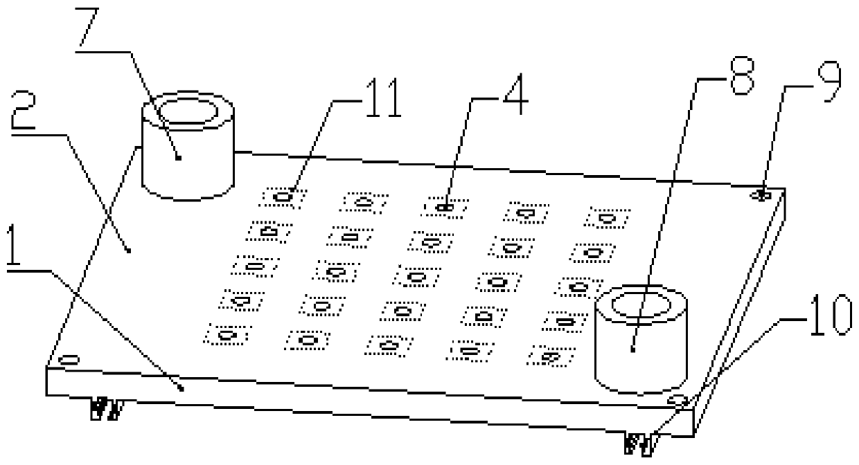
[0041] A radiator, including a heat exchange container for heat exchange and conduction with a heat source, and a liquid injection port 7 and a liquid outlet 8 for the heat exchange liquid to flow into and out of the heat exchange container, and the inside of the heat exchange container is provided with a gradually increasing The flow channel for reducing the fluid pressure drop and performing heat exchange, the liquid injection port 7 is located at the largest end of the flow channel in the heat exchange container, and the liquid outlet 8 is located at the smallest end of the flow channel in the heat exchange container.

[0042] Description of the heat exchange container: The heat exchange container is the same as the existing technology, which can ensure that the heat exchange container can isolate the heat source and the heat exchange heat body. For the heat exchange tubes used in the shell-and-tube heat exchangers and tube-sheet heat exchangers in the prior art, it is only ...

Embodiment 2

[0045] The difference between this embodiment and Embodiment 1 is that: 1) a structure of a heat exchange container is provided; 2) a specific structure is provided in which the circulation channel in the heat exchange container is gradually enlarged; The specific heat dissipation scene of the channel is optimized to design the heat dissipation structure; 4) optimize the design of the location of the liquid injection port 7 and the liquid outlet port 8 so that the heat exchange liquid can fully flow through the heat exchange container.

[0046] The repeated parts of this embodiment and Embodiment 1 will not be repeated, and only the differences are pointed out here:

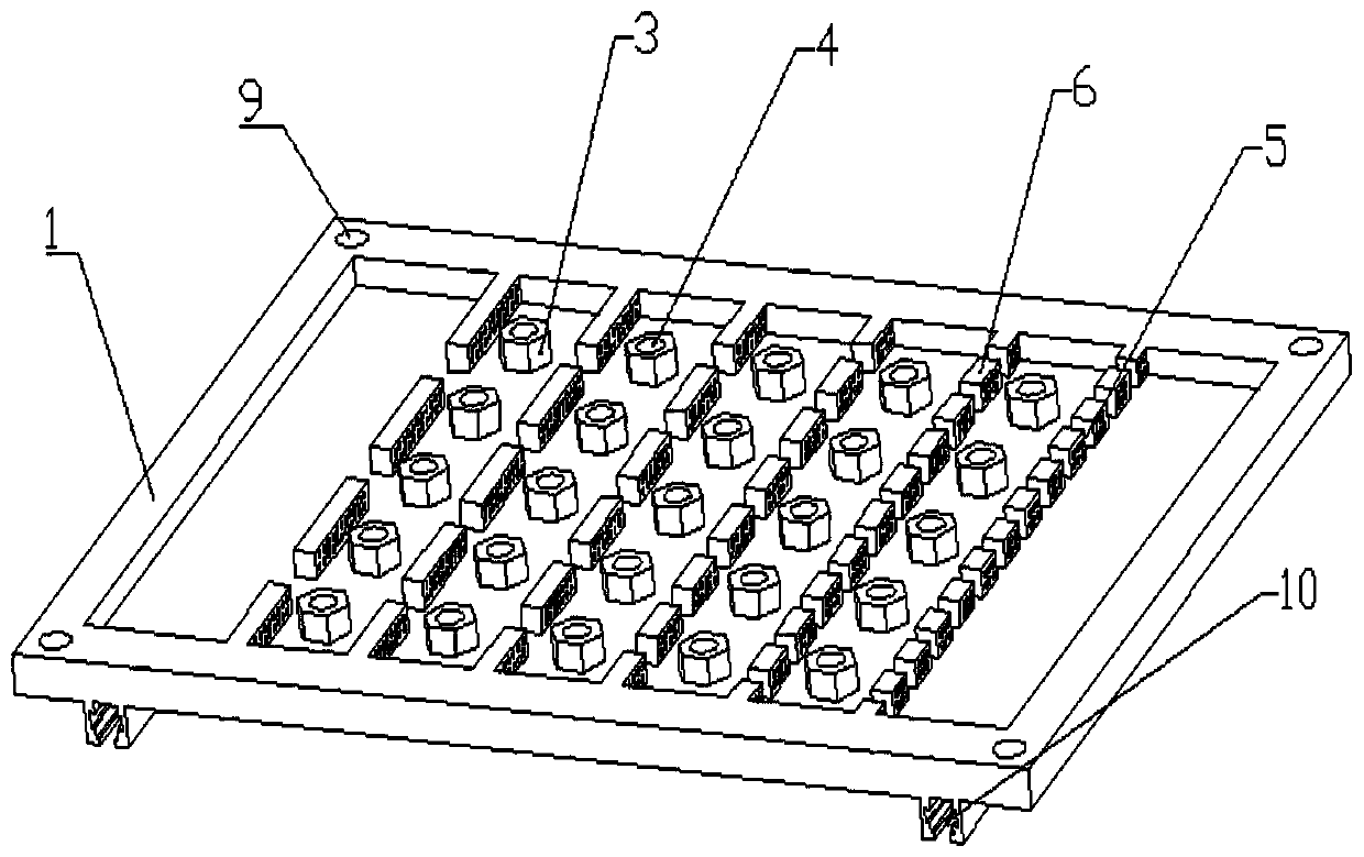
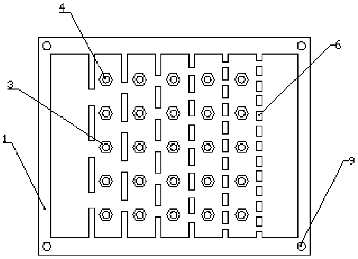
[0047] 1) In order to specifically provide a structural form of a heat exchange container, see figure 1 and figure 2 In this embodiment, the heat exchange container is plate-shaped and consists of a cold plate 1 and a cover plate 2 which are combined with each other to form a closed space, and the closed space ...

Embodiment 3

[0054] The difference between this embodiment and Embodiment 2 is: Embodiment 2 is for heat dissipation for a 5×5 phased array antenna, while this embodiment is for heat dissipation for an 8×8 phased array antenna. See Figure 5 However, the difference between this embodiment and Embodiment 2 is only that the number of partitions 6 and the number of heat exchange units have been adjusted correspondingly with respect to Embodiment 2.

[0055] By analogy, the present invention can not only be used for 5×5 phased array antennas or 8×8 phased array antennas to dissipate heat, but also can be used for more types of phased array antennas to dissipate heat. This time, they will not be described in detail. As long as the heat sink structure of the present invention is used to dissipate heat from the phased array antenna, it should be included in the protection scope of the present application.


PUM


Abstract

The invention relates to the field of heat dissipation, in particular to a micro-channel radiator, integrated manufacturing and an application of the micro-channel radiator in a control array antenna.The radiator is manufactured through 3D printing. Through a fluid channel which is distributed in a gradually changed manner and a liquid injection port and a liquid outlet which are respectively formed at the biggest end and the smallest end of the flow channel, cooling liquid uniformly passes through the whole fluid channel. When the radiator is in use, the highest temperature of the radiator is 298K, the lowest temperature of the radiator is 295K, and the temperature difference after heat dissipation is 3 DEG C. Compared with a pure runner structure, the radiator is stronger in heat dissipation capability and more uniform in temperature distribution after heat dissipation, and has the characteristics of good heat dissipation performance and temperature uniformity, one-time forming, noneed of using a nut sealing ring and the like for packaging.

Description

technical field [0001] The invention relates to the field of heat dissipation, in particular to a radiator, a method for manufacturing the radiator and a heat dissipation device for a microchannel of a controlled array antenna. Background technique [0002] With the development of electronic systems towards miniaturization and integration, integrated multi-functional electronic systems and devices have emerged. With the improvement of the integration of various original devices, the packaging density is getting smaller and smaller, and the heat flux density of the electronic system has increased sharply. Electronic systems with small size, light weight and efficient heat dissipation are required, and the motherboards and cooling systems of existing electronic equipment are required. The traditional air cooling technology can no longer meet the heat dissipation requirements of high heat flux devices. The efficient liquid cooling technology can not only meet the electrical sig...

Claims


Application Information

Patent Timeline
Patent Type & Authority Applications(China)
IPC IPC(8): H01Q1/00H01Q21/00H01Q21/06
CPCH01Q1/02H01Q21/00H01Q21/061
Inventor 徐尚龙陈鹏艳谢俊明徐冲陈亮
Owner UNIV OF ELECTRONICS SCI & TECH OF CHINA
Why Eureka
Try Eureka