Novel voltage-multiplying-Z source inverter

A source inverter, a new type of technology, applied in the field of new voltage doubler-Z source inverter, can solve the problems of reducing work efficiency, increasing circuit complexity, and high DC link voltage peaks, so as to reduce production costs and failure rates, The overall structure design is reasonable and the effect of increasing the probability density

Pending Publication Date: 2019-08-23
QINGDAO TECHNOLOGICAL UNIVERSITY
View PDF0 Cites 1 Cited by
  • Summary
  • Abstract
  • Description
  • Claims
  • Application Information

AI Technical Summary

Problems solved by technology

On this basis, the inverter modulation factor is also larger, and a higher inverter voltage gain can be obtained. However, the high turn ratio of the coupled inductor will cause large leakage inductance and series resistance and other bad parameters, which will not only make the work The efficiency is reduced, and the energy released by the leakage inductance will cause a large DC link voltage peak, the inverter effect is poor, and the circuit performance is affected
The Γ-type Z-source inverter (Γ-ZSI ) also improves the boost ratio by introducing coupled inductors. Similar to the Trans-ZSI coupled winding structure, the structure of the coupled inductor module will also cause the peak of the DC link voltage to be too high
If the above problems are not solved, multi-level circuits can be cascaded to obtain higher voltage gain under the condition of smaller direct duty cycle, but this increases the number of components in the circuit and increases the complexity of the circuit. Reduced work efficiency

Method used


Image

  • Novel voltage-multiplying-Z source inverter
  • Novel voltage-multiplying-Z source inverter
  • Novel voltage-multiplying-Z source inverter

Examples


Embodiment

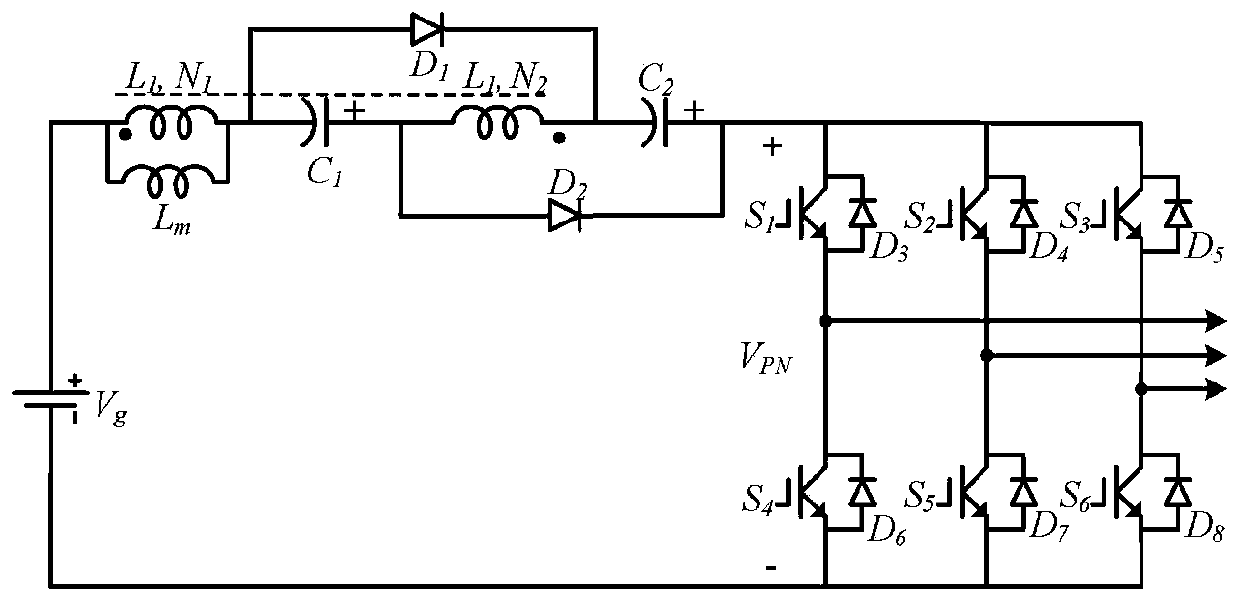
[0022] The main structure of the novel voltage doubler-Z source inverter involved in this embodiment is as follows: figure 1 shown, including: DC power supply V g , by the first winding L 1 and the second winding L 2 Composed of coupled inductors, the first capacitor C 1 and a second capacitor C 2 , the first diode D 1 , the second diode D 2 and a three-phase bridge inverter circuit unit, wherein the second winding L of the coupled inductor 2 and the first winding L 1 The turns ratio is n=N 2 :N 1 , in order to more specifically represent the model of the coupled inductance, figure 1 shows the magnetizing inductance of the coupled inductor as L m ; The first winding L of the coupled inductor 1 The terminal of the same name and the DC power supply V g The positive pole is connected, and the other end is connected to the first capacitor C 1 The cathode and the first diode D 1 Connected to the positive terminal, the first capacitor C 1 positive pole and the second ...


PUM


Abstract

The invention belongs to the field of DC-AC inversion equipment, and relates to a novel voltage-multiplying-Z source inverter. A dotted terminal of the first winding is connected with the positive electrode of the DC power supply, and the other end of the first winding is connected with the negative electrode of a first capacitor and the positive electrode of a second diode. The positive electrodeof the first capacitor is connected with the non-dotted terminal of a second winding and the negative electrode of a second diode, and the dotted terminal of the second winding is connected with thenegative electrode of the first diode and the negative electrode of the second capacitor. The positive electrode of the second capacitor is connected with the negative electrode of the second diode. Athree-phase voltage type bridge inverter circuit unit consists of six power switching tubes with anti-parallel diodes, and is used for receiving a switch signal provided by external equipment. The inverter is reasonable in overall structural design and simple to operate, the number of components is reduced through the combined structure of the boost circuit and the inverter circuit, the probability density of the circuit is improved, the production cost and the failure rate are reduced, and the high-gain boost inverter is suitable for high-gain boost inversion occasions.

Description

[0001] Technical field: [0002] The invention belongs to the technical field of DC-AC inverter equipment, and in particular relates to a novel voltage doubler-Z source inverter. [0003] Background technique: [0004] At present, the energy crisis and the aggravation of environmental pollution have prompted the rapid development of renewable energy. Solar energy, as one of the clean renewable energy sources, has considerable development prospects. The traditional photovoltaic power generation system outputs the output voltage of photovoltaic cells connected in series to the power grid using DC / AD inverters, but the multi-level structure has high production costs and failure rates. On this basis, a DC / DC boost converter is added between the photovoltaic cell and the grid to complete the boost first, and then perform the inversion, but this DC / DC-DC / AC structure will lead to a complex system structure and low working efficiency. Inferior question. [0005] The document Peng F...

Claims


Application Information

Patent Timeline
Patent Type & Authority Applications(China)
IPC IPC(8): H02M7/5387H02M3/06
CPCH02M3/06H02M7/5387
Inventor 丁新平刘贇赵德林郝杨阳李恺李海滨房成群赵振伟
Owner QINGDAO TECHNOLOGICAL UNIVERSITY
Why Eureka
Try Eureka