
Gas uniform-distribution type premixing burner

A premixed combustion and uniform distribution technology, which is applied to gas fuel burners, burners, combustion methods, etc., can solve problems such as uneven temperature distribution on the combustion surface and poor gas mixing, so as to improve the uniformity of gas distribution, The effect of enhancing the uniformity of mixing

Pending Publication Date: 2019-09-03
周吉成
View PDF2 Cites 1 Cited by
  • Summary
  • Abstract
  • Description
  • Claims
  • Application Information

AI Technical Summary

Problems solved by technology

[0007] In view of the above technical problems, the embodiment of the present invention solves the problems of poor gas mixing and uneven temperature distribution on the combustion surface in the prior art by providing a gas uniform distribution premix burner

Method used


Image

  • Gas uniform-distribution type premixing burner
  • Gas uniform-distribution type premixing burner
  • Gas uniform-distribution type premixing burner

Examples


Embodiment 1

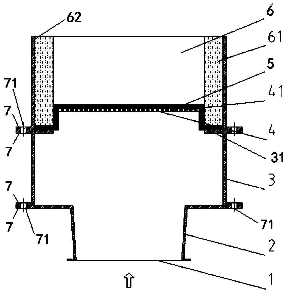
[0025] Depend on figure 1 As shown, the present invention includes a premix gas inlet, a diffusion chamber, a mixing chamber, a gas equalization plate, a metal fiber surface, and a flue.

[0026] A gas uniform distribution type premix burner, including a diffusion chamber with a premixed gas inlet, a mixing chamber, a gas uniform plate, a metal fiber surface and a flue arranged in sequence along the gas direction and fixedly connected as a whole; The inlet of the premixed gas is arranged at the gas inlet end below the diffusion chamber; the outlet of the diffusion chamber is connected to the mixing chamber; the gas uniform plate is located between the mixing chamber and the surface of the metal fiber; the flue is located outside the surface of the metal fiber.

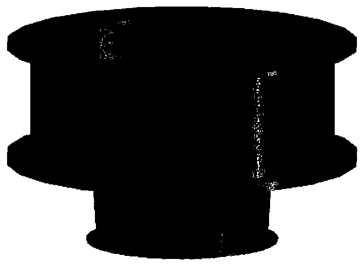
[0027] Such as figure 2 As shown, the shape of the diffusion chamber is a truncated cone with a cone angle of 15°.

[0028] The shape of the mixing chamber is cylindrical, matching with the truncated cone of the dif...

Embodiment 2

[0036] The difference from Example 1 is:

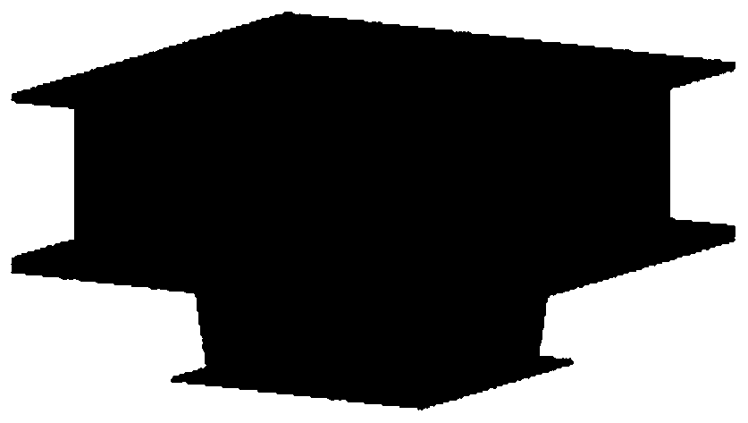
[0037] Such as image 3 As shown, the shape of the diffusion chamber is a truncated pyramid with a cone angle of 21°.

[0038] The shape of the mixing chamber is a quadrangular prism, matching with the truncated quadrangular pyramid of the diffusion chamber.

[0039] The cross-sectional area of ​​the mixing chamber is 1.5 times the cross-sectional area of ​​the outlet of the diffusion chamber.

[0040] The arrangement of the through pores is a regular triangle or a regular quadrilateral, the center distance is 3 mm, and the hole diameter is 2 mm.

[0041] All the other contents are the same as in Example 1.

[0042] After the fuel gas and air are mixed, they enter the diffusion chamber from the premixed gas inlet. The cone angle of the diffusion chamber is 21°. The specific cone angle can separate the flow boundary layer, thereby avoiding the large velocity gradient of the fluid on the axial cross section. Make the fluid velocity ...


PUM

PropertyMeasurementUnit
Cone angleaaaaaaaaaa
Center distanceaaaaaaaaaa
Apertureaaaaaaaaaa

Abstract

The invention discloses a gas uniform-distribution type premixing burner. The gas uniform-distribution type premixing burner comprises a diffusion chamber with a premixing gas inlet, a mixing chamber,a gas equalizing plate, a metal fiber surface and a flue which are sequentially arranged in the gas moving direction and are fixedly linked into a whole, the premixed gas inlet is formed in the gas inlet end of the lower part of the diffusion chamber, an outlet of the diffusion chamber is connected with the mixing chamber, the gas equalizing plate is positioned between the mixing chamber and themetal fiber surface, and the flue is positioned on the outer side of the metal fiber surface. The method has the advantages that the mixing uniformity of the premixing gas is enhanced, the gas distribution uniformity of the combustion surface is improved, then the combustion efficiency reaches 99.99% or above, and the emission of NOx is less than 15 ppmv (calculated based on 3% oxygen)

Description

technical field [0001] The invention relates to the technical field of fully premixed porous surface combustion, in particular to a gas uniformly distributed premixed burner, which is suitable for efficient and clean combustion of organic waste gas. Background technique [0002] Due to the poor thermal conductivity and radiation performance of the gas, the traditional combustion characterized by a free flame inevitably has disadvantages such as uneven temperature distribution, narrow combustion area, and excessive pollutant emissions. The premixed combustion method in porous media is a process in which a gas mixture is burned in a special porous media material with high temperature resistance and good thermal conductivity. Premixed combustion method Full premixed porous surface combustion has the characteristics of fast combustion speed and short flame. Under the condition of small excess air coefficient, complete combustion can be achieved, and the emission of CO and NOx is...

Claims


Application Information

Patent Timeline
IPC IPC(8): F23D14/02F23D14/62
CPCF23D14/02F23D14/62
Inventor 周吉成晁锦峰
Owner 周吉成
Learn More