Method for monitoring online condition of IGBT module bonding wire

A bonding wire and state technology, applied in the fields of power electronics and electronic information science, can solve the problems of low precision, not describing the measurement of the collector-emitter voltage drop value of the IGBT module, and not considering the change of the working conditions of the IGBT.

Active Publication Date: 2019-09-10
HEFEI UNIV OF TECH
View PDF7 Cites 18 Cited by
  • Summary
  • Abstract
  • Description
  • Claims
  • Application Information

AI Technical Summary

Problems solved by technology

[0003] The patent application document with the application number 201410072990.X and the publication number 104880657A discloses a fault detection method for IGBT devices and the corresponding detection circuit. Comparators corresponding to the number of bonding wires are set up, and the gate voltage signal is used to judge the fault of the IGBT. The number of bonding wires falling off, but the detection circuit is more complicated and the accuracy is not high
The patent application document with the application number 201710318198.1 and the publication number 107621782A discloses a fault diagnosis method for an IGBT module. By measuring the collector-emitter voltage drop value of the IGBT module in real time, the least squares support vector machine model with quantum ant colony optimization is used. Diagnoses the health status of the IGBT module, but does not consider the impact of changes in working conditions on the IGBT, and does not explain how to measure the collector-emitter voltage drop of the IGBT module

Method used


Image

  • Method for monitoring online condition of IGBT module bonding wire
  • Method for monitoring online condition of IGBT module bonding wire
  • Method for monitoring online condition of IGBT module bonding wire

Examples


Embodiment Construction

[0053] The present invention will be further described below in combination with specific embodiments and accompanying drawings.

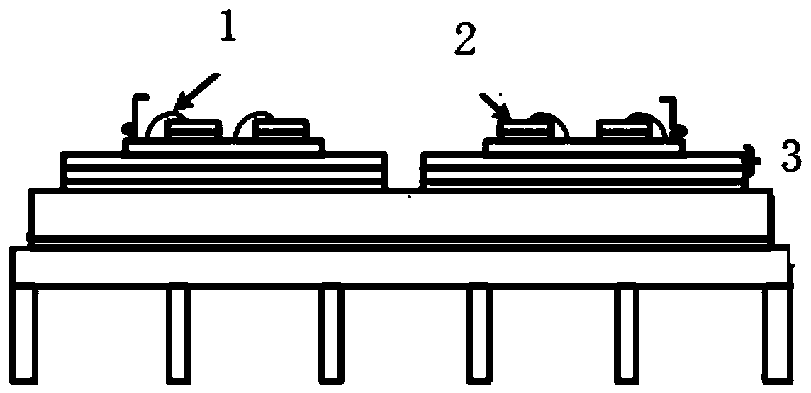
[0054] In this embodiment, the SKM50GB12T4 power module of the SEMKRON series is used for experimental verification, and six bonding wires are used to connect the chip and the substrate in parallel.

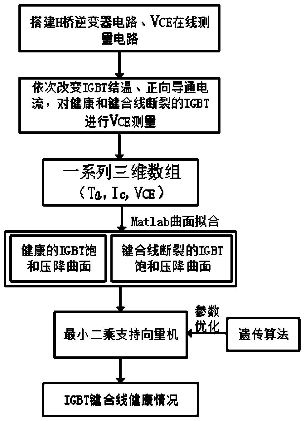
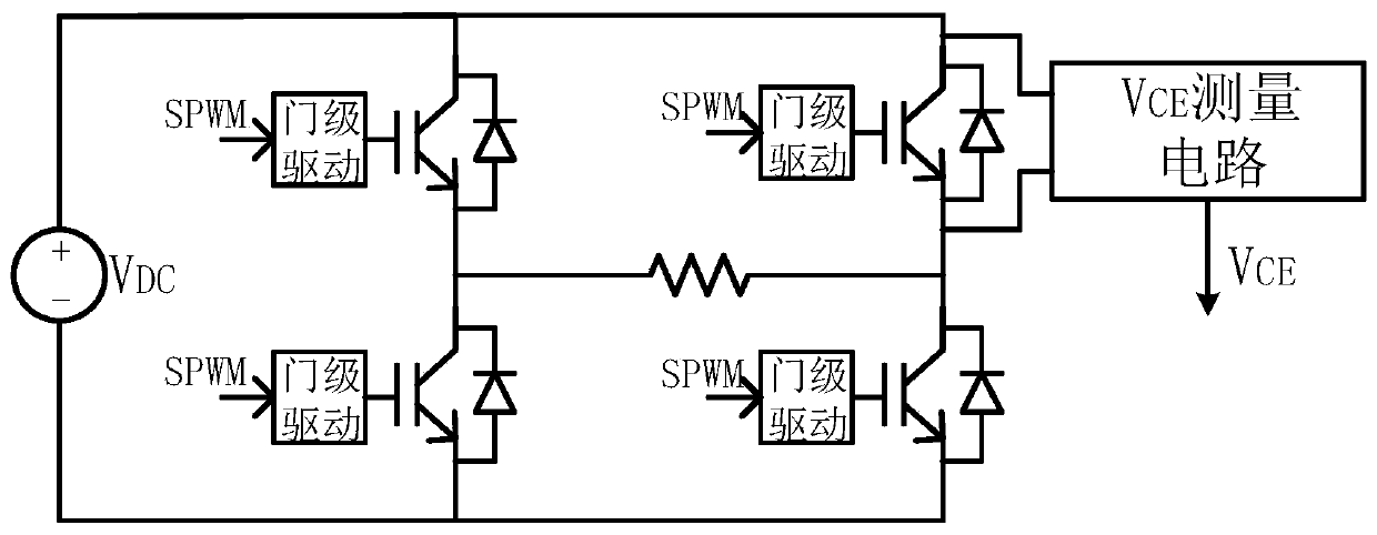
[0055] Such as figure 1 As shown, the present invention provides a method for online state monitoring of IGBT module bonding wires, as follows image 3 The shown full-bridge inverter circuit is taken as an example to introduce the implementation process of this method in detail. The specific implementation steps are as follows:

[0056] Step 1. Build the full-bridge inverter circuit and V CE In-line measurement circuit, the V CE The two input terminals of the online measurement circuit are connected to the collector and emitter of the IGBT power module of the full-bridge inverter circuit to realize the connection between the full-bridge inverter ci...


PUM


Abstract

A method for monitoring online condition of an IGBT module bonding wire comprises the following steps of step 1, building a full-bridge inverter circuit and a VCE online measurement circuit, and connecting both input terminals of the VCE online measurement circuit to the collector and emitter of the IGBT power module of the full-bridge inverter circuit to realize the connection between the full-bridge inverter circuit and the VCE online measurement circuit; step 2, establishing a three-dimensional data model of the healthy IGBT; step 3, establishing an IGBT three-dimensional data model of thebond wire break; step 4, optimizing the least squares support vector machine by a genetic algorithm; and step 5, using the optimized least squares support vector machine to evaluate the state of the 3D data model obtained in the steps 2 and 3. The method provided by the invention closely links the online monitoring and state evaluation, and helps to improve the health management mechanism of the IGBT module bonding wire.

Description

technical field [0001] The invention relates to the fields of power electronics and electronic information science, in particular to a method for online state monitoring of IGBT module bonding wires, which utilizes a genetic algorithm to optimize the least squares support vector machine to evaluate the health of the IGBT bonding wires. Background technique [0002] Power converters are widely used in the fields of smart grid, rail transit and new energy, and the insulated gate bipolar transistor (IGBT) is the core device of the power converter, and its reliability is the guarantee for the safe operation of the system. Therefore, the IGBT On-line monitoring and status assessment are extremely important. Solder layer fatigue and bond wire detachment are the two main failure modes of IGBTs. Due to the continuous improvement of solder layer technology, IGBT module bond wire failure has received extensive attention. [0003] The patent application document with the application n...

Claims


Application Information

Patent Timeline
Patent Type & Authority Applications(China)
IPC IPC(8): G01R31/26G06N3/12H02M7/5387
CPCG01R31/2601G01R31/2642G06N3/126H02M7/5387H01L2224/73265H01L2224/48091H01L24/48H01L2924/13055H01L2924/00014H01L2224/48227G01R31/66G01R31/2608H01L2224/32225H01L2924/00012H01L2224/45099G01R19/10H01L2224/48225
Inventor 何怡刚李凯伟何鎏璐李志刚
Owner HEFEI UNIV OF TECH
Why Eureka
Try Eureka