PDMS micro-fluidic chip mould copying method

A microfluidic chip, replication method technology, applied in chemical instruments and methods, laboratory utensils, laboratory containers, etc. The effect of promoting rapid development and wide application

Pending Publication Date: 2019-09-13
CHONGQING UNIV
View PDF4 Cites 9 Cited by
  • Summary
  • Abstract
  • Description
  • Claims
  • Application Information

AI Technical Summary

Problems solved by technology

[0004] (1) The traditional glass microfluidic chip manufacturing process is long, costly and unsafe
[0005] (2) Traditional hard polymer microfluidic chip production requires complex mold processing and relies on expensive hot pressing or injection molding equipment, which is not suitable for ordinary laboratories or start-up small businesses
[0006] (3) In the traditional PDMS microfluidic chip manufacturing process, the brittleness of the silicon base and the interface stress between the photoresist and the silicon base lead to damage to the male mold during use.
[0007] (4) Due to some uncontrollable factors in the photolithography process, even if the same instrument and process parameters are used, there will be subtle structural differences between molds made in different batches (especially the height of the mold), which will affect the experiment. result
[0010] Although microfluidic technology has shown outstanding technical advantages and good application prospects, due to the high cost, low efficiency and lack of mature large-scale production technology of microfluidic chips, the low cost and one-time use of this technology are greatly limited. Applications in the field of daily testing, such as medical diagnosis, environmental monitoring, food safety testing, etc.

Method used


Image

  • PDMS micro-fluidic chip mould copying method
  • PDMS micro-fluidic chip mould copying method
  • PDMS micro-fluidic chip mould copying method

Examples


Embodiment 1

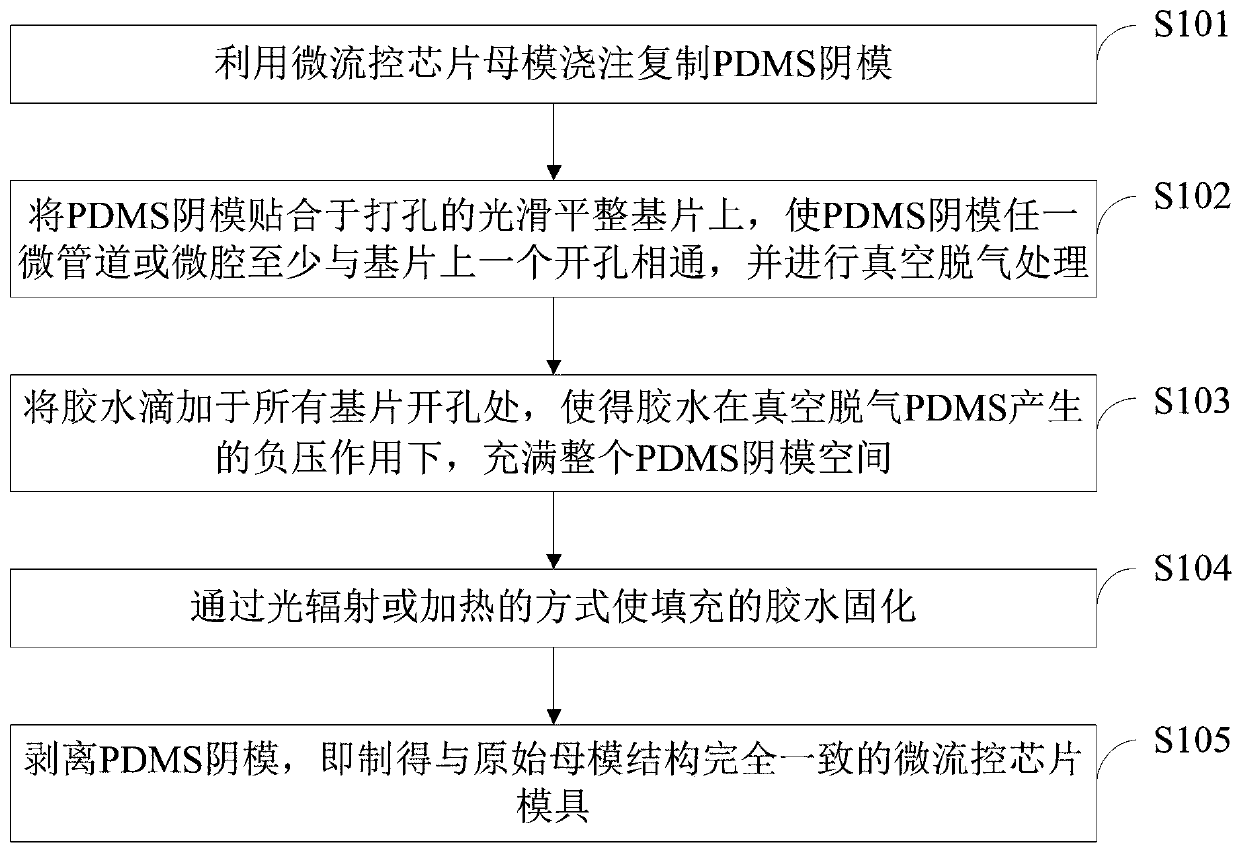
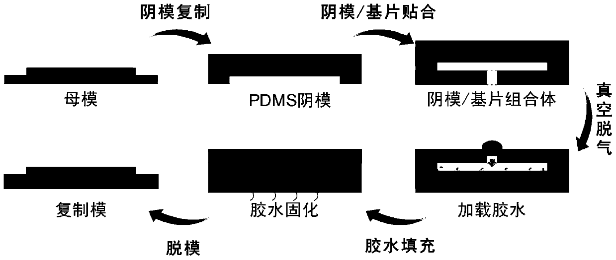
[0053] Such as image 3 As shown, based on the method of the present invention, a microfluidic chip mold integrating 1 micropipe and 10 microcavities is copied and manufactured for capturing droplets or microspheres. The specific steps are:

[0054] (1) Production of PDMS negative mold: First, mix a certain amount of PDMS precursor and cross-linking agent at a ratio of 10:1, and vacuum defoam, and then pour the PDMS prepolymer after vacuum defoaming on the microfluidic chip master mold , and heated on a 90°C hot plate for 1 hour to achieve PDMS curing; after the PDMS is cured, it is peeled off from the chip master mold to obtain a PDMS negative mold.

[0055] (2) Substrate preparation: In order to ensure that one micropipe and its 10 microcavities in series can be quickly and effectively filled with glue in the PDMS female mold, so as to realize the complete replication of the mold. First, use an ultrasonic puncher to make through holes with a diameter of 1.5 mm at the substr...

Embodiment 2

[0062] Such as Figure 4 As shown, based on the method of the present invention, a microfluidic chip mold integrating 40 micropipes and 20,000 microcavities is copied and manufactured for digital PCR research. The specific steps are:

[0063] (1) Production of PDMS negative mold: First, mix a certain amount of PDMS precursor and cross-linking agent at a ratio of 10:1, and vacuum defoam, and then pour the PDMS prepolymer after vacuum defoaming on the microfluidic chip master mold , and heated on a 90°C hot plate for 1 hour to achieve PDMS curing; after the PDMS is cured, it is peeled off from the chip master mold to obtain a PDMS negative mold.

[0064] (2) Substrate preparation: In order to ensure that the 40 microchannels of the PDMS female mold and the 20,000 microcavities connected in series can be quickly and effectively filled with glue, so as to realize the complete replication of the mold. First, use a glass knife to describe three independent microgrooves on a specifi...

Embodiment 3

[0071] Such as Figure 5 As shown, based on the method of the present invention, a microfluidic chip mold integrating 5000 independent microcavities and no connected micropipes is copied and manufactured for single-cell research. The specific steps are:

[0072] (1) Production of PDMS negative mold: First, mix a certain amount of PDMS precursor and cross-linking agent at a ratio of 10:1, and vacuum defoam, and then pour the PDMS prepolymer after vacuum defoaming on the microfluidic chip master mold , and heated on a 90°C hot plate for 1 hour to achieve PDMS curing; after the PDMS is cured, it is peeled off from the chip master mold to obtain a PDMS negative mold.

[0073] (2) Substrate preparation: In order to ensure that the 5,000 microcavities of the PDMS female mold can be quickly and effectively filled with glue, so as to realize the complete replication of the mold. First, according to the arrangement of the chip structure, use a laser marking machine to describe horizon...


PUM

PropertyMeasurementUnit
diameteraaaaaaaaaa

Abstract

The invention belongs to the technical field of micronano-fabrication and discloses a PDMS micro-fluidic chip mould copying method. A micro-fluidic chip master mould is utilized to cast and copy a PDMS female mould; the PDMS female mould is attached to a perforated smooth and flat substrate to make any microchannel or micro-cavity of the PDMS female mould to be communicated with at least one holeof the substrate, and then vacuum degassing treatment is performed; glue is dropwise added at all the holes of the substrate such that the whole space of the PDMS female mould is filled with the glueunder the negative pressure generated by vacuum degassing of PDMS; the glue is solidified through an optical radiation or heating mode; and the PDMS female mould is removed to prepare a micro-fluidicchip mould which has a completely consistent structure as the original master mould. According to the invention, rapid, low-cost and high-fidelity copy of the PDMS chip mould can be realized. The method of the invention is conducive to realize mass production of PDMS micro-fluidic chips and is helpful for promoting rapid development and wide application of the PDMS micro-fluidic chips.

Description

technical field [0001] The invention belongs to the technical field of micro-nano manufacturing, and in particular relates to a PDMS microfluidic chip mold replication method. Background technique [0002] In recent years, due to the advantages of miniaturization, low sample consumption, high throughput, and portability, microfluidic chips have shown good performance in many fields such as biomedical research, clinical testing, chemical synthesis, environmental monitoring, health quarantine, and judicial identification. application prospects. At present, according to the production materials, there are three main types of microfluidic chips: PDMS chips, hard polymer chips (PMMA, PC, COC, etc.) It is realized by hydrofluoric acid wet etching, the whole production process is long, costly, and involves dangerous chemicals; while hard polymer microfluidic chips usually use microelectronics technology combined with electroplating to make positive molds, and then combined with in...

Claims


Application Information

Patent Timeline
Patent Type & Authority Applications(China)
IPC IPC(8): B01L3/00
CPCB01L3/502707
Inventor 李刚武银崔旭谢腾宝
Owner CHONGQING UNIV
Why Eureka
Try Eureka