
Sludge dewatering pretreatment apparatus and sludge dewatering pretreatment method

A pretreatment device, sludge dewatering technology, applied in sludge treatment, water/sludge/sewage treatment, dewatering/drying/concentrated sludge treatment, etc. To avoid problems such as large wear and tear of chemical equipment, to achieve the effect of saving secondary concentration costs, high sludge dewatering efficiency, and reducing operating costs

Pending Publication Date: 2019-09-13
湖南北控威保特环境科技股份有限公司
View PDF0 Cites 6 Cited by
  • Summary
  • Abstract
  • Description
  • Claims
  • Application Information

AI Technical Summary

Problems solved by technology

Land use due to excessive heavy metals leads to poor paths; landfill is a temporary transitional technical route, which is combined with front-end deep dehydration and has become the route with the most application cases at this stage, but the addition of chemicals is large, and the sludge increment is obvious, and There is secondary pollution; the utilization of building materials is due to the high moisture content of sludge and the small amount of mixing, and the addition of a large amount of chemicals to the front-end dehydration leads to strong corrosion of the sludge. At present, many collaborative cement projects have been shut down; incineration is currently the most effective way to solve the sludge problem. The thorough method is also the most mainstream technology for sludge disposal in the world. However, the sludge in my country has low calorific value, high moisture content, and large sediment content. The traditional drying equipment wears a lot, and the operation and maintenance are complicated, resulting in high drying costs.

Method used


Image

  • Sludge dewatering pretreatment apparatus and sludge dewatering pretreatment method

Examples


Embodiment Construction

[0031] In order to facilitate the understanding of the present invention, the present invention will be described in more detail below in conjunction with the accompanying drawings and preferred embodiments, but the protection scope of the present invention is not limited to the following specific embodiments.

[0032] Unless otherwise defined, all technical terms used hereinafter have the same meanings as commonly understood by those skilled in the art. The terminology used herein is only for the purpose of describing specific embodiments, and is not intended to limit the protection scope of the present invention.

[0033] Unless otherwise specified, various raw materials, reagents, instruments and equipment used in the present invention can be purchased from the market or prepared by existing methods.

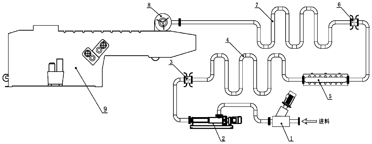
[0034] A sludge dewatering pretreatment device of a specific embodiment of the present invention, such as figure 1 As shown, it includes a mechanical crushing pretreatment d...


PUM


Abstract

The invention discloses a sludge dewatering pretreatment apparatus and a sludge dewatering pretreatment method. The apparatus comprises a mechanical crushing pretreatment device, a sludge transfer pump, a first sludge and reagent mixer, a first serpentine tube, an ultrasonic reactor, a second sludge and reagent mixer, a second serpentine tube, a stirring device and a concentrating filter press; the mechanical crushing pretreatment device is used for crushing block impurities in the sludge, and the outlet of the mechanical crushing pretreatment device is connected with the sludge transfer pump;the first sludge and reagent mixer is connected with the sludge transfer pump and the first serpentine tube respectively, and is used for mixing a sludge conditioning reagent with the sludge; the ultrasonic reactor is arranged on the outer wall of a pipeline between the first serpentine tube and the second sludge and reagent mixer; the second sludge and reagent mixer is connected with the secondserpentine tube, and is used for mixing a flocculant with the sludge; and the inlet of the stirring device is connected with the second serpentine tube, and the outlet of the stirring device is connected with the concentrating filter press. The method has the advantages of short sludge conditioning time, completeness in sludge modification, and high sludge dewatering efficiency.

Description

technical field [0001] The invention belongs to the technical field of sludge treatment, and in particular relates to a sludge dehydration pretreatment device and method. Background technique [0002] The national sludge production scale is huge, but the harmless disposal rate is low. Existing sludge disposal routes include land use, landfill, building material utilization, incineration, etc. Land use due to excessive heavy metals leads to poor paths; landfill is a temporary transitional technical route, which is combined with front-end deep dehydration and has become the route with the most application cases at this stage, but the addition of chemicals is large, and the sludge increment is obvious, and There is secondary pollution; the utilization of building materials is due to the high moisture content of sludge and the small amount of mixing, and the addition of a large amount of chemicals to the front-end dehydration leads to strong corrosion of the sludge. At present, ...

Claims


Application Information

Patent Timeline
Patent Type & Authority Applications(China)
IPC IPC(8): C02F11/143C02F11/122C02F11/15C02F11/123C02F11/127C02F11/125
CPCC02F11/14C02F11/122C02F11/123C02F11/127C02F11/125
Inventor 刘阳胡晓明陈代新任巍王丹胡柳
Owner 湖南北控威保特环境科技股份有限公司
Learn More