
Method for producing turbocharger shell for wet-type casting vehicle

A turbocharger shell and vehicle turbine technology, which is applied to casting molding equipment, casting molds, cores, etc., can solve the problems of low production efficiency, high design requirements, low pass rate, etc., and achieve production cost reduction, The filling process is stable and the effect of simplifying the production process

Inactive Publication Date: 2019-09-17
成都艾特安科技有限公司 +1
View PDF3 Cites 3 Cited by
  • Summary
  • Abstract
  • Description
  • Claims
  • Application Information

AI Technical Summary

Problems solved by technology

However, due to the high performance requirements of the turbocharger housing, and the volute casting 1 is relatively complex, the wall thickness is uneven, and there are many thin-walled places. The thickness of the thickest part is 15mm, and the minimum wall thickness is about 2.8mm. Belongs to complex thin-walled shell castings
Turbocharger housing castings are required to have good airtightness, no shrinkage and shrinkage defects on the inner and outer surfaces, high surface finish, accurate dimensions, and poor fluidity of ductile iron or high alloy steel in actual pouring
Therefore, using the traditional sand casting method for production requires extremely high design requirements for the gating system 4, and it is very easy to cause turbulent flow, unstable mold filling, and insufficient feeding due to unreasonable design of the gating system 4, resulting in cold shut, Defects such as shrinkage cavity, shrinkage porosity, and sand sticking lead to problems such as too many defects, low pass rate, and poor product quality in the production of volute castings. Therefore, the traditional sand casting method is currently used to produce turbocharger casing volutes. There are very few manufacturers of shell castings 1
For this reason, the prior art proposes a three-box molding, inclined pouring turbocharger housing wet casting method, which overcomes the common problems of sand casting to produce turbocharger housings to a certain extent, reducing However, the following problems still exist: 1) Due to the use of three-box molding, the process complexity is greatly increased, and it is also easy to cause the shape of the volute casting 1 to be misaligned due to poor box closing; 2) The pouring method with an inclination of 15° is adopted , which increases the manual labor intensity during pouring, and it is also easy to cause sand loss due to moving the sand box; 3) Only one piece is produced in one box, the production efficiency is low, and the sand iron ratio is high, which is not conducive to reducing production costs and saving sand resources
However, the wet casting currently used is prone to some casting defects, such as: sand inclusions, scars, rat tails, sticky sand, pores, trachoma, sand swelling, etc.

Method used


Image

  • Method for producing turbocharger shell for wet-type casting vehicle
  • Method for producing turbocharger shell for wet-type casting vehicle
  • Method for producing turbocharger shell for wet-type casting vehicle

Examples


Embodiment 1

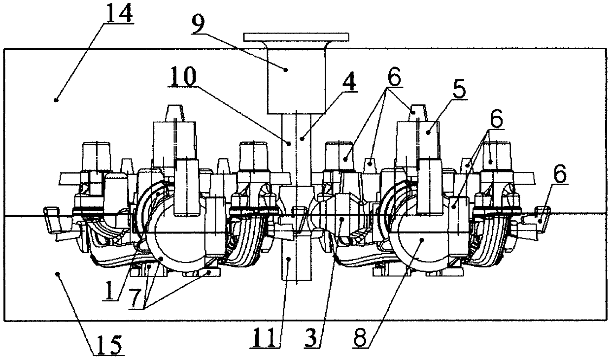
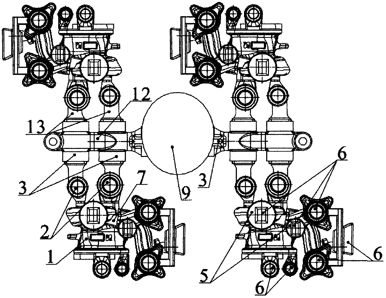
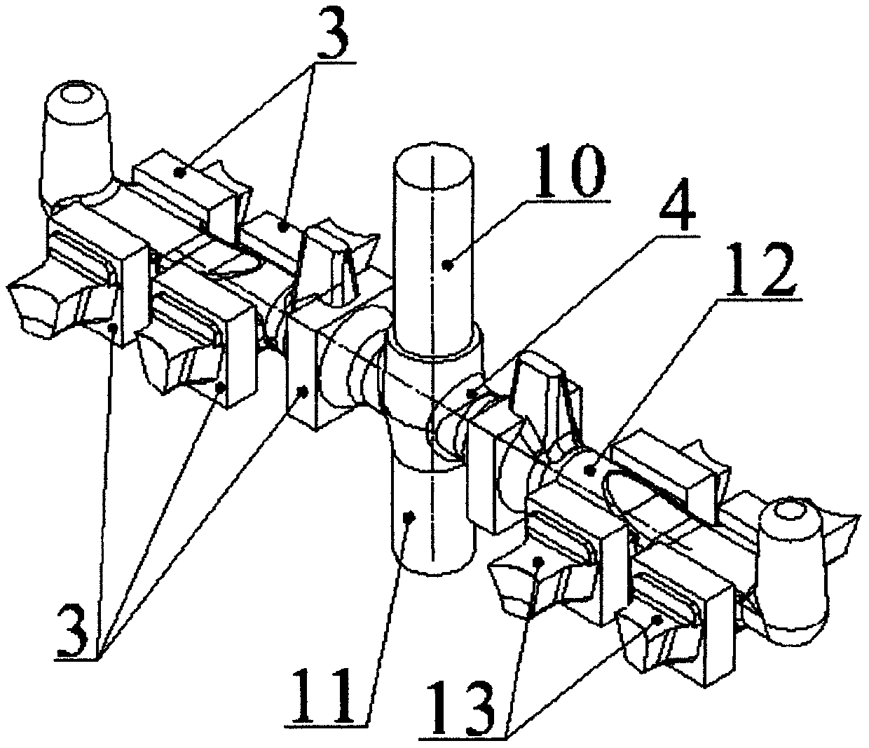
[0041] The traditional green mold sand is used for molding, and two boxes of molding technology are used, with four pieces in one box, arranged symmetrically in the center. There is a sprue 10 connecting the upper sand box and the lower sand box in the middle of the sand mold; a runner 10 is set at the bottom of the sprue 10; a special sprue nest with a rectangular longitudinal section is set at the end of the sprue 10 11; An inner sprue is provided at the far end of the runner. Wherein, each volute casting 1 communicates with the volute casting 1 through two inrunners. During the molding process, the composition ratio of green mold sand used is calculated by weight percentage: new sand 70%, old sand 26.8%, moisture 2.6%, component A 0.6%, component B 0%. Among them, component A is 53% natural sodium base + 20% artificial sodium base + 27% coal powder, and component B is 30% artificial sodium base + 70% coal powder.

[0042] In order to ensure the stability of mold filling u...

Embodiment 2

[0049] In the modeling, the traditional green mold sand is used for modeling. Two-box modeling technology is adopted, four pieces in one box, arranged symmetrically in the center. Set a sprue 10 connecting the upper sand box and the lower sand box in the middle of the sand mold; set a runner 10 at the bottom of the sprue 10; set a special sprue nest 11 with a rectangular longitudinal section shape at the end of the sprue 10; An inrunner is provided at the far end of the runner.


PUM


Abstract

The invention discloses a method for producing a turbocharger shell for a wet-type casting vehicle. According to the method, raw sand resources can be remarkably saved, and the casting technology difficulty is reduced. According to the technical scheme, the method for producing the turbocharger shell for the wet-type casting vehicle comprises the following steps that a traditional damp mold sand is used for modeling, a straight runner is used as the center in a sand mold, and sand boxes are symmetrically arranged, wherein each sand box is provided with four pieces; the straight runner communicates with an upper sand box and a lower sand box, and a cross runner is arranged at the bottom end of the straight runner, and a pouring gate nest with a rectangular longitudinal section shape is arranged at the tail end of the cross runner, and meanwhile, inner runners are arranged at the far end of the cross runner, and each volute casting communicates with other volute castings through two inner runners; ceramic filter sheets and follow-up cold iron are placed on the sand core lower cores on the two sides of the symmetric straight runner, so that the core making is completed; the follow-up cold iron is placed at a hot joint part, linking to the runners, of the bottom of each volute; simulation results of the defects of shrinkage porosity and shrinkage cavity are combined and compared to determine the optimal process parameters; and finally, in the medium-frequency induction furnace, molten metal enters from top to bottom through a gate cup and enters a mold cavity from different inner gates, thus complete the filling.

Description

technical field [0001] The invention relates to the field of turbochargers, in particular to the technical field of production methods of turbocharger housings for automobiles, in particular to a wet casting method for producing turbocharger housings for automobiles. Background technique [0002] Turbochargers are widely used in large agricultural, engineering, mining machinery trucks, large buses and ships. Turbochargers can increase the power of automobile engines, reduce fuel consumption, reduce noise and pollution, and effectively improve engine power, economy and environmental performance. In many gasoline and diesel engines, turbocharger technology is used in order to continuously improve the efficiency of the engine, reduce exhaust emissions and save fuel. Turbocharging (Turbocharger) is a technology that uses the exhaust gas generated by the operation of an internal combustion engine to drive an air compressor (Air-compressor). Simply put, a turbocharger is an air ...

Claims


Application Information

Patent Timeline
IPC IPC(8): B22C9/02B22C9/08B22C21/02B22C9/20B22C9/22B22C9/10B22D15/02
CPCB22C9/02B22C9/082B22C9/086B22C9/088B22C9/108B22C9/20B22C9/22B22C21/02B22D15/02
Inventor 王黎晖杨屹唐勇
Owner 成都艾特安科技有限公司
Learn More