Supercharge Your Innovation With Domain-Expert AI Agents!

Photoelectric hybrid airtight cabin crossing socket

A photoelectric hybrid and airtight technology, which is applied in the direction of electrical components, optical waveguide coupling, and parts of connecting devices, can solve the problem of the inability to simultaneously plug and unplug the electrical and optical fiber contacts, and the optical fiber contacts have long dimensions, The problem of large insertion loss of the airtight socket is achieved to overcome the large insertion loss, reduce the loss of the optical path, and achieve the effect of reliable sealing

Inactive Publication Date: 2019-09-20
SHANGHAI AEROSPACE SCI & IND ELECTRIC APPLIANCE RES INST
View PDF9 Cites 0 Cited by
  • Summary
  • Abstract
  • Description
  • Claims
  • Application Information

AI Technical Summary

Problems solved by technology

However, the optical fiber cannot use glass sintering technology due to its low working temperature. At present, the optical path sealing mainly adopts the metallization of the optical fiber, and the alloy welding sealing method is used between the shell and the shell. Compared with the traditional epoxy glue seal and O-ring seal, this method has more advantages. It has the characteristics of reliable sealing and strong temperature shock resistance, but it has the disadvantages that the optical fiber contact piece is too long in size, unable to realize simultaneous plugging and unplugging of electrical and optical fiber contact pieces, metallization of bare optical fiber, and easy damage to optical fiber by welding
In recent years, there is also a method of welding and sealing the glass light guide rod with the shell alloy after metallization. This method can solve the shortcomings of the welding and sealing method of the bare optical fiber, but its transmission optical path is "optical fiber-collimating lens-light guide rod-focusing lens ——optical fiber”, there are 4 non-contact spatial couplings in total, the coupling efficiency is low, and the insertion loss of the airtight socket is large

Method used


Image

  • Photoelectric hybrid airtight cabin crossing socket
  • Photoelectric hybrid airtight cabin crossing socket
  • Photoelectric hybrid airtight cabin crossing socket

Examples


Embodiment Construction

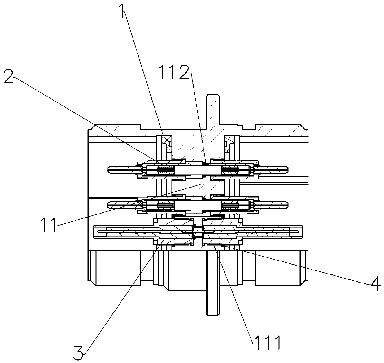
[0026] refer to figure 1 , The present invention includes a shell, 1, an optical fiber ferrule fitting 2 and a radio frequency ferrule fitting 3.

[0027] refer to figure 1 , the housing 1 is a circular housing member, the middle of which is radially provided with a partition wall 11, and the partition wall 11 is provided with several optical fiber pin holes 112 and several radio frequency pin holes 111, and the optical fiber pin holes 112 Both ends are provided with internal threads, and both ends of the radio frequency pin hole 111 are provided with internal threads.

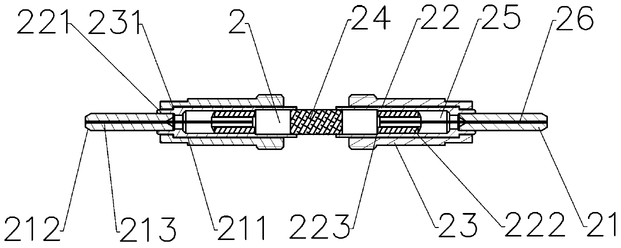
[0028] refer to figure 1 , figure 2 , the optical fiber ferrule assembly 2 is composed of a lens 24 and an optical fiber assembly, wherein the optical fiber assembly is composed of a ceramic sleeve 21, an inner sleeve 22, a coaxial through hole 222, an outer sleeve 23, an optical fiber 26 and an epoxy glue 25, The outer casing 23 is provided with external threads;

[0029] The inner casing 22 is arranged...


PUM


Abstract

The invention discloses a photoelectric hybrid airtight cabin crossing socket, which comprises a shell body, an optical fiber pin assembly and an RF pin assembly, wherein a partition wall is arranged on the shell body, an optical fiber pin hole and an RF pin hole are formed in the partition wall, the optical fiber pin assembly is arranged in the optical fiber pin hole, the RF pin assembly is arranged in the RF pin hole, and the sealing of the optical fiber pin assembly, the RF pin assembly and the partition wall is realized by adopting an AuSn alloy welding manner. The photoelectric hybrid airtight cabin crossing socket adopts the photoelectric hybrid airtight cabin crossing technology, its optical path adopts an ''optical fiber-self-focusing lens-optical fiber'' optical path transmission mode, the optical path loss is reduced, the technical problem of large insertion loss caused by welding a light guiding rod with a sealed cabin crossing socket is overcame, and the photoelectric hybrid airtight cabin crossing socket has the advantages of reliable sealing, good photoelectric performance and good environmental adaptability.

Description

technical field [0001] The invention relates to the technical field of communication, in particular to a photoelectric hybrid airtight through-cabin socket. Background technique [0002] The airtight cabin penetrating socket is a key component to solve the application of signal transmission technology in the space environment. Harsh environmental influences. With the construction of the space station and the continuous upgrading of the space integrated radar system, the transmission of space pictures and video information makes the data volume and processing speed of the system more and more demanding. The traditional high-speed electrical connector signal transmission technology can no longer meet the requirements. It is imperative for optical fiber communication technology to enter the space application system. In addition, electronic equipment for space gradually proposes requirements for miniaturization, integration, and modularization. Simultaneous transmission of opt...

Claims


Application Information

Patent Timeline
IPC IPC(8): G02B6/38H01R13/46H01R13/52
CPCG02B6/3817G02B6/3825G02B6/3853G02B6/3869H01R13/46H01R13/521
Inventor 赵苏琨张光王文理
Owner SHANGHAI AEROSPACE SCI & IND ELECTRIC APPLIANCE RES INST
Features
  • R&D
  • Intellectual Property
  • Life Sciences
  • Materials
  • Tech Scout
  • Unparalleled Data Quality
  • Higher Quality Content
  • 60% Fewer Hallucinations
Learn More