A kind of laser ultrasonic technology assisted pulse laser drilling device and method

An auxiliary pulse and laser drilling technology, which is applied in laser welding equipment, metal processing equipment, welding equipment, etc., can solve the problems of large thermal influence, recasting layer thickness, etc., to improve efficiency, uniform range, and improve drilling quality Effect

Active Publication Date: 2021-01-15
JIANGSU UNIV
View PDF10 Cites 0 Cited by
  • Summary
  • Abstract
  • Description
  • Claims
  • Application Information

AI Technical Summary

Problems solved by technology

[0004] In order to solve the problems of thicker recasting layer, larger heat-affected zone and microcracks in current pulse laser drilling, the present invention provides a pulse laser drilling device and method assisted by laser ultrasonic technology

Method used


Image

  • A kind of laser ultrasonic technology assisted pulse laser drilling device and method
  • A kind of laser ultrasonic technology assisted pulse laser drilling device and method
  • A kind of laser ultrasonic technology assisted pulse laser drilling device and method

Examples


Embodiment 1

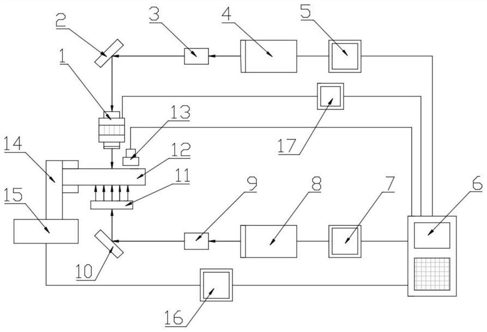
[0040] A laser ultrasonic technology-assisted pulse laser drilling device, characterized in that it includes a vibration module 1, a first reflective plane mirror 2, a first beam expander 3, a first pulse laser 4, a first pulse laser controller 5, and a computer 6 , second pulse laser controller 7, second pulse laser 8, second beam expander 9, second reflective plane mirror 10, beam splitter 11, workpiece 12, ultrasonic detector 13, fixture 14, working platform 15, working platform Controller 16, vibration module controller 17;

[0041] The first reflective plane mirror 2 is located at the top, and directly below it are the vibration module 1, the workpiece 12, the beam splitter 11 and the second reflective plane mirror 10; the workpiece 12 is fixed on the fixture 14, and the fixture 14 is fixed on the working platform 15; the ultrasonic probe 13 is installed on the upper side of the workpiece 12, not in contact with the workpiece 12; one end of the working platform controller...

Embodiment 2

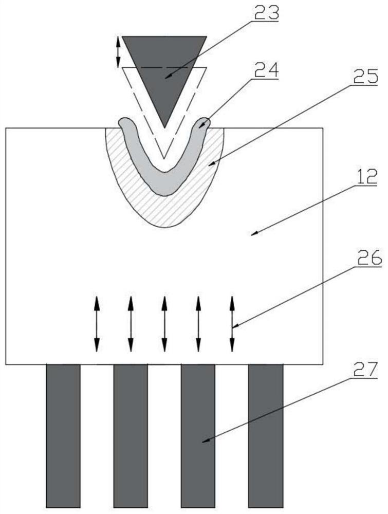
[0048] A laser ultrasonic technology-assisted pulse laser drilling method, before the first pulse laser 4 outputs the first laser beam 23 to process the workpiece 12, during the processing and for a period of time after processing, on the one hand, the second pulse laser 8 is used to output the first laser beam 23 Two laser beams, the second laser beam 27 after passing through the beam splitter acts on the lower surface of the workpiece 12, and part of the energy is absorbed by the material surface and converted into heat energy, causing the surface temperature of the material to rise rapidly, thereby causing the material to expand. The strain field and stress field are formed through the thermoelastic effect, thereby exciting high-frequency ultrasonic waves, which generate ultrasonic vibrations to assist laser drilling, promote the removal of molten materials in laser drilling, improve drilling efficiency, and reduce the thickness and microstructure of the recast layer. Cracks...


PUM


Abstract

The invention discloses a device and method for assisting pulsed laser drilling through a laser ultrasonic technology, and relates to the field of laser drilling. The device comprises a vibration module, a first pulse laser, a computer, a second pulse laser controller, a second pulse laser, an ultrasonic detector and a vibration module controller; on the basis of the principle, the method comprises the steps that before a workpiece is machined by the first pulse laser, during machining and after a period of time of the machining, the second pulse laser is adopted for acting on the lower surface of the workpiece to stimulate an ultrasonic wave, the ultrasonic wave generates ultrasonic vibration to assist in laser drilling, a vibration module is adopted for generating ultrasonic vibration, and the focal point after laser focus output by the first pulse laser vibrates up and down according to a certain frequency. The problems that at present, the pulse laser drilling recast layer is heavy, the heat influence area is large, and micro-cracks exist are solved, the workpiece has the higher machining quality, meanwhile, the drilling depth can be improved, and the machining efficiency is greatly improved.

Description

technical field [0001] The invention relates to the field of laser drilling, in particular to a pulse laser drilling device and method assisted by laser ultrasonic technology. Background technique [0002] Laser drilling is a very important laser processing application technology. Focusing the laser beam through the focusing lens can obtain a small diameter spot and form a high temperature at the focal point. Under the action of the pulsed laser, the material is continuously melted and evaporated. Finally, the gas and the plasma formed by the hole will generate high pressure to blow the impurities out of the hole, forming micropores. Compared with the traditional mechanical drilling method, laser drilling has unique advantages and irreplaceable functions, such as high efficiency, high precision, no mechanical stress and no tool loss, etc. It has become one of the key technologies in the field of modern micro-hole processing . [0003] However, during the pulse laser drill...

Claims


Application Information

Patent Timeline
Patent Type & Authority Patents(China)
IPC IPC(8): B23K26/382B23K26/70B23K26/00
CPCB23K26/00B23K26/0093B23K26/382B23K26/70B23K26/702
Inventor 夏凯波任乃飞王后孝石春辉李涛田佳男柳苏洋
Owner JIANGSU UNIV
Why Eureka
Try Eureka