Micro-channel boiling heat transfer system and method based on vapor-liquid multiphase fluid staggered division

A boiling heat transfer, multiphase fluid technology, applied in fluid velocity measurement, process for producing decorative surface effects, microstructure technology, etc. The pressure drop increases, the surface roughness decreases, etc., to achieve strong scientific innovation and technical practicability, increase the gas-liquid contact area, and achieve the effects of sensible heat and latent heat

Pending Publication Date: 2019-09-27
NORTH CHINA ELECTRIC POWER UNIV (BAODING)
View PDF7 Cites 17 Cited by
  • Summary
  • Abstract
  • Description
  • Claims
  • Application Information

AI Technical Summary

Problems solved by technology

[0003] (1) Whether it is a silicon-based microchannel evaporator to be used for electronic chips or a metal-based evaporator used in the industrial field, due to the reduction of the channel scale, the processing technology adopted is more precise than the conventional large-scale heat exchanger, For example, the silicon-based micro-evaporator is processed by MEMS technology, and the metal-based micro-channel evaporator is processed by precision machine tools and laser processing. Due to the improvement of processing accuracy and the reduction of surface roughness, the size of the nucleation hole of the micro-channel evaporator is relatively small. , the wall superheat required for the gas-liquid phase transition in the microchannel is inversely proportional to the size of the nucleation cavity, therefore, a smaller nucleation cavity size leads to a higher wall superheat, resulting in the start-up overheating phenomenon of the boiling system;
[0004] (2) At a relatively high wall superheat, the liquid is also in a highly superheated metastable state. Once the nucleation occurs at the nucleation cavity, the bubbles grow rapidly to fill the flow interface of the entire microchannel, and the superheated metastable state The energy stored in the liquid is concentrated and quickly released through the limited gas-liquid interface, resulting in rapid expansion of the gas-liquid interface, causing large fluctuations in flow, pressure drop, temperature, etc. in the channel, and the gas-liquid interface may even flow back to the storage liquid at the entrance of the channel slot, which poses a challenge to the stable operation of the microchannel heat exchanger
[0006] Arranging a throttling device at the inlet to eliminate instability will lead to an increase in the pressure drop of the entire microchannel evaporator. Although it can partially suppress the fluid backflow during the gas-liquid phase transition process in the channel, the gas-liquid in the channel after the throttling device The vibration and temperature fluctuation problems of the interface still cannot be effectively solved

Method used


Image

  • Micro-channel boiling heat transfer system and method based on vapor-liquid multiphase fluid staggered division
  • Micro-channel boiling heat transfer system and method based on vapor-liquid multiphase fluid staggered division
  • Micro-channel boiling heat transfer system and method based on vapor-liquid multiphase fluid staggered division

Examples


Embodiment 1

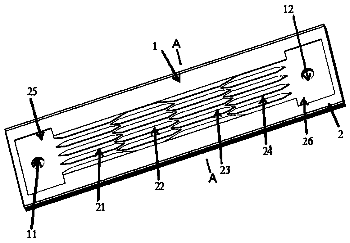
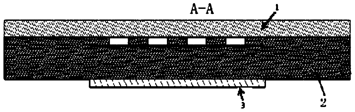
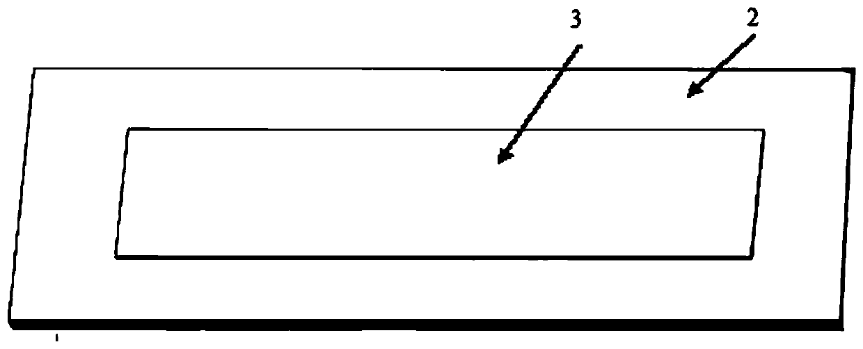
[0028] like Figure 1-4Shown is a microchannel boiling heat transfer system based on gas-liquid multiphase fluid staggered division, which consists of an upper cover plate 1 , a bottom fluid-based microchannel array plate 2 and a simulated heat source 3 . The upper cover plate has a liquid inlet 11 and a liquid outlet 12; the bottom layer has a first parallel microchannel array 21, a second parallel microchannel array 21, and a second parallel microchannel array plate 2 that are periodically staggered and arranged on the front of the microchannel array plate 2 based on fluid staggered divisions. Channel array 22, the third parallel microchannel array 23, the fourth parallel microchannel array 24, the inlet liquid storage tank 25 and the outlet liquid storage tank 26; The back side is facing the first parallel microchannel array 21, the second parallel microchannel array 22, the third parallel microchannel array 23, and the fourth parallel microchannel array 24 regions arranged...

Embodiment 2

[0039] like Figure 5 Shown is a microchannel boiling heat transfer enhancement method based on interlaced division of gas-liquid multiphase fluid. The single-phase liquid working medium enters the first parallel microchannels arranged in periodic interlaced divisions from the liquid inlet 11 through the inlet storage tank 25 Array 21, the second parallel microchannel array 22, the third parallel microchannel array 23, and the fourth parallel microchannel array 24. Under the heating heat flow of the simulated heat source 3, the working medium is periodically staggered and arranged in the microchannel array 21, Gas-liquid phase transition occurs in 22, 23, and 24 to form a multiphase flow, and the first parallel microchannel array 21, the second parallel microchannel array 22, the third parallel microchannel array 23, and the fourth parallel microchannel array 24 mutually The staggered area produces fluid segmentation, boundary layer detachment and redevelopment respectively, a...


PUM


Abstract

The invention discloses an enhanced heat transfer system and method, and belongs to the field of micro evaporators. The enhanced heat transfer system is composed of an upper cover plate, a periodic staggered micro-channel array plate and a simulation heat source. A liquid working medium enters the staggered micro-channel array and is heated to generate gas-liquid phase change, the gas-liquid two-phase working medium is periodically divided in the staggered micro-channel array, and meanwhile, five types of enhanced heat transfer modes are realized: (1) the gas-liquid contact area is increased through gas-phase division, so that latent heat exchange is increased; (2) superheated liquid energy is released from more gas-liquid interfaces, so that the interface expansion rate is reduced, and flow and thermal instability caused by rapid expansion of the interface are fundamentally inhibited; (3) bubble segmentation delays heat transfer deterioration caused by the fact that a large-area steam film covers a heating surface; (4) a bubble tail turbulent flow area is increased, and convection heat exchange is enhanced; and (5) periodical separation and re-development of the heat boundary layer of the near-wall area occur through periodical division of the liquid phase, the heat exchange resistance of the near-wall area is remarkable, and convection heat exchange is improved.

Description

technical field [0001] The invention belongs to the technical field of microchannel phase change heat transfer, in particular to a microchannel boiling heat transfer system and method based on interlaced division of vapor-liquid multiphase fluid. Background technique [0002] With the development of micro-nano-scale technology, the size of electronic components is getting smaller and smaller, the degree of integration is getting higher and higher, the heat flux of the chip is increasing sharply, and the highest heat flux of highly integrated chips can reach 100W / cm 2 , put forward higher demands on the thermal management of the chip. Studies have shown that every 10°C increase in chip temperature reduces reliability by 50%. Therefore, the reliability of electronic components increases, and there is an urgent need to develop high heat flux density electronic chip cooling technology. The micro-channel evaporator has the advantages of compact structure, large specific surface ...

Claims


Application Information

Patent Timeline
Patent Type & Authority Applications(China)
IPC IPC(8): B81B7/00B81C1/00H01L23/473
CPCB81B7/0093B81C1/00119H01L23/473
Inventor 张伟于俊杰郭明宇刘广林徐进良
Owner NORTH CHINA ELECTRIC POWER UNIV (BAODING)
Why Eureka
Try Eureka