Casting system and casting method of cylinder barrel

A technology for cylinders and castings, which is applied in the field of casting systems for cylinders, to achieve the effects of accelerating cooling speed, improving machining accuracy, and reducing casting defects

Active Publication Date: 2019-10-11
宁波拓铁机械有限公司
View PDF9 Cites 2 Cited by
  • Summary
  • Abstract
  • Description
  • Claims
  • Application Information

AI Technical Summary

Problems solved by technology

[0004] The present invention aims at the above-mentioned deficiencies of the prior art, and provides a casting whose wall thickness is not prone to shrinkage and loose defects, especially between the sup

Method used


Image

  • Casting system and casting method of cylinder barrel
  • Casting system and casting method of cylinder barrel
  • Casting system and casting method of cylinder barrel

Examples


Embodiment 1

[0053] (1) Weigh 600kg of pig iron, 100kg of scrap steel, and 2.5kg of recarburizer;

[0054] (2) First add 2.5kg recarburizer, then put all the pig iron and steel scrap into the smelting furnace; heat to melt the charge, add 9kg of FeSi75-C ferrosilicon after the charge is melted, add 1.4kg of electrolytic copper, The original molten iron is obtained, and the original molten iron is continued to be heated to 1530 °C; the composition and mass percentage of the obtained original iron liquid are C 3.74%, Si 1.65%, Mn0.12%, P 0.033%, S 0.012%, Cu0. 18%, the rest is iron;

[0055] (3) Carry out spheroidization by the flushing method, add 10kg of nodulizing agent; add inoculant with the flushing method, and inoculate the former molten iron, the addition of the inoculant is 3.5kg, stir evenly, and obtain molten iron; The composition and mass percentage of the molten iron are C3.69%, Si 2.40%, Mn 0.12%, P 0.033%, S 0.0095%, Cu 0.18%, CE (carbon equivalent) 4.5%, and the rest is iron...

Embodiment 2

[0061] (1) Weigh 630kg of pig iron, 70kg of scrap steel, and 2.1kg of recarburizer;

[0062] (2) First add 2.1kg recarburizer, then put all the pig iron and steel scrap into the smelting furnace; heat to melt the charge, add 9.5kg of FeSi75-C ferrosilicon after the charge is melted, and add 1.12kg of electrolytic copper , to obtain the original molten iron, continue to heat the original molten iron to 1520 ° C; the composition and mass percentage of the obtained original iron liquid are C 3.80%, Si 1.67%, Mn0.15%, P 0.035%, S 0.011%, Cu0 .15%, the remainder being iron;

[0063] (3) Carry out spheroidization by the flushing method, add 9.5kg of nodularizing agent; add inoculant with the flushing method, and inoculate the former molten iron, the addition of the inoculant is 3.15kg, stir evenly, and obtain molten iron; The composition and mass percent of this molten iron are C3.72%, Si 2.52%, Mn 0.15%, P 0.035%, S 0.009%, Cu 0.15%, CE (carbon equivalent) 4.57%, and the rest is i...


PUM


Abstract

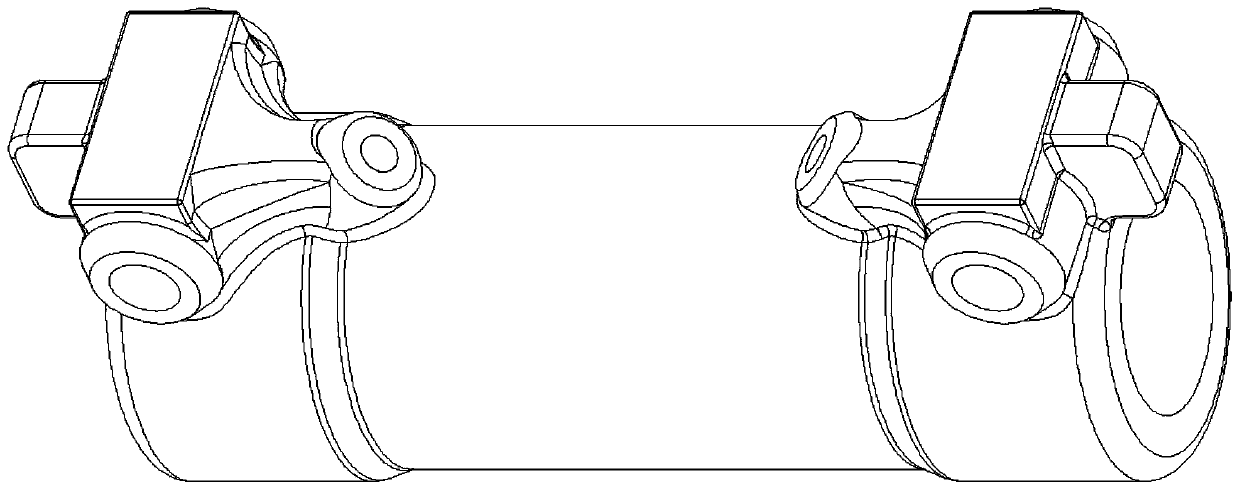
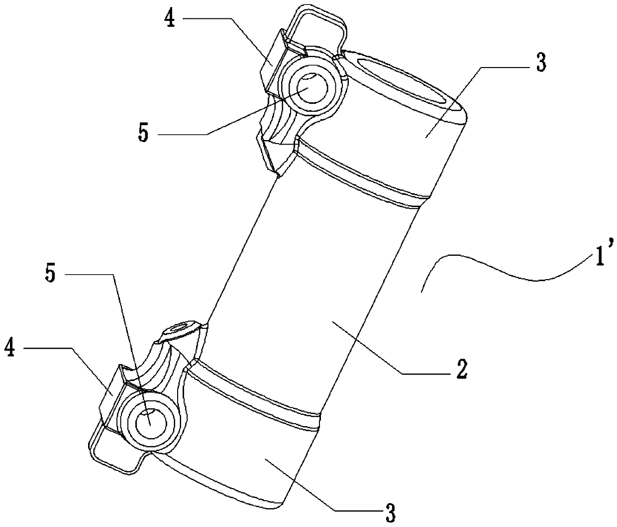
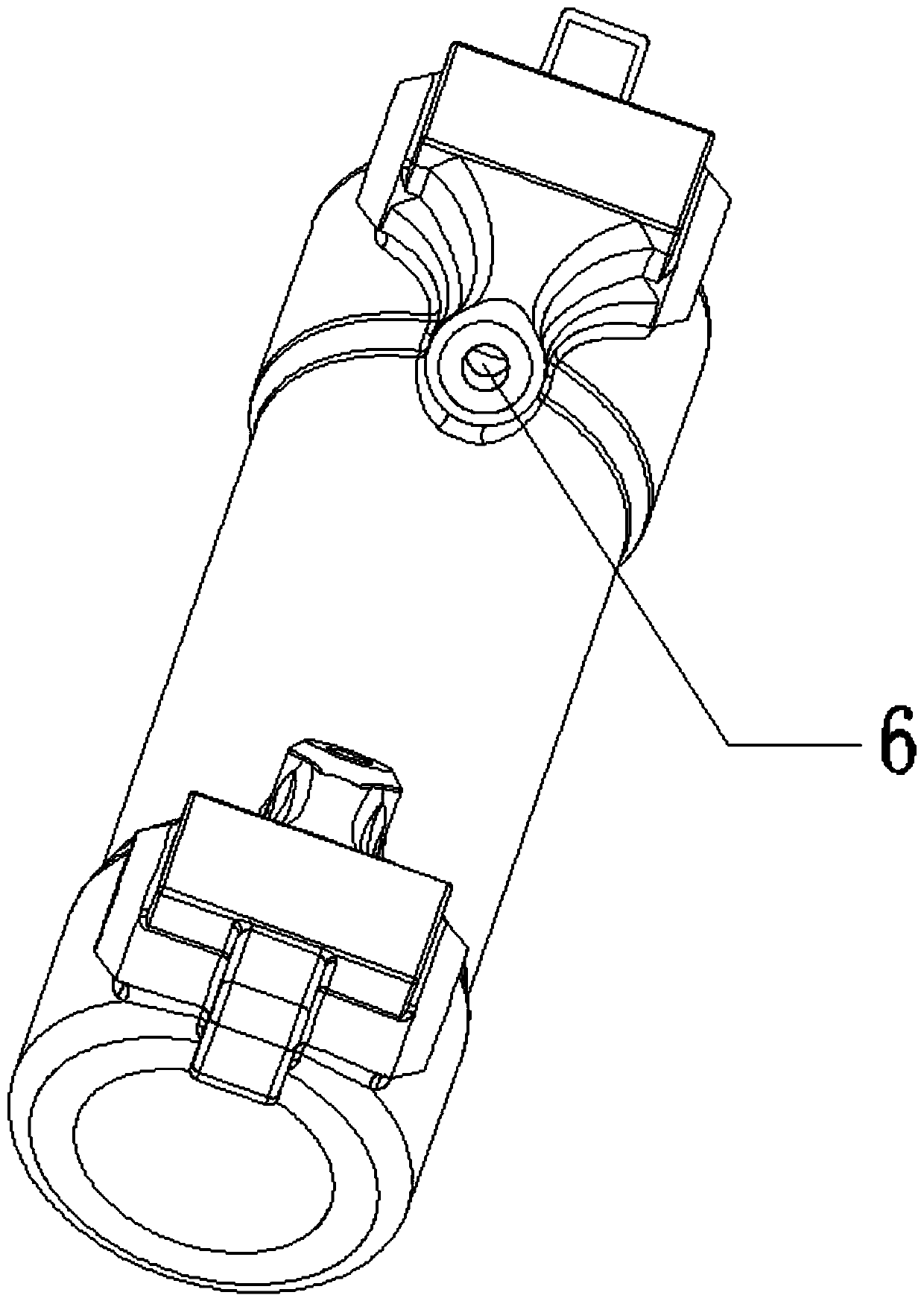
The invention discloses a casting system and casting method of a cylinder barrel. The casting system comprise a casting mold cavity and a pouring system, wherein the casting cavity comprises a cylinder barrel cavity body, a through hole is axially formed in the cylinder barrel cavity body, the cylinder barrel cavity body is composed of a cylinder barrel head part and a middle body part, the diameter of the cylinder barrel head part is larger than that of the middle body part, a radial protruding block is arranged on the cylinder barrel head part, and a supporting fixing hole and an oil passagehole are formed in the protruding block; the pouring system comprises a sprue, a transverse runner and an inner sprue, the sprue vertically communicates with the transverse runner, the two ends of the transverse runner communicate with the inner sprue through risers, and the inner sprue communicates with a convex block of the casting cavity; and the supporting fixing hole is filled with a first sand core, and an axial through hole of the cylinder barrel cavity body is filled with a second sand core. The casting system has the advantages that parts with the wall thickness of a casting are notprone to shrinkage and loosening defect generating, particularly, the casting defect is not easy to occur among the supporting fixing hole, the oil passage hole and the inner surface of the cylinder barrel, and a chill structure cannot be easily generated in parts with the thin wall thickness.

Description

technical field [0001] The invention relates to the technical field of cylinder barrel casting in hydraulic cylinders, in particular to a cylinder barrel casting system and casting method. Background technique [0002] A hydraulic cylinder is a hydraulic actuator that converts hydraulic energy into mechanical energy and performs linear reciprocating motion (or swing motion). When it is used to realize reciprocating motion, the deceleration device can be eliminated, and there is no transmission gap, and the motion is stable, so it is widely used in various mechanical hydraulic systems. The hydraulic cylinder is basically composed of cylinder barrel and cylinder head, piston and piston rod, sealing device, buffer device and exhaust device. Among them, the cylinder barrel is the main component of hydraulic cylinders, single props, hydraulic supports, gun barrels and other products, and the quality of its castings directly affects the life and reliability of the entire product....

Claims


Application Information

Patent Timeline
IPC IPC(8): B22C9/24B22C9/08C21C1/10C22C33/10C22C37/04C22C37/10
CPCB22C9/08B22C9/24C21C1/10C22C33/10C22C37/04C22C37/10
Inventor 宋贤发张亚敏吴超项铮宇伍林俞争史军民
Owner 宁波拓铁机械有限公司
Why Eureka
Try Eureka