
Thermoplastic thermistor composite material with positive temperature coefficient and preparation method thereof

A positive temperature coefficient and composite material technology, which is applied to resistors with positive temperature coefficients, resistors, non-adjustable metal resistors, etc., can solve the problems of complex procedures, increased density, high resistivity, etc., and achieve simple manufacturing methods, Enhanced conductivity and less conductive filler

Active Publication Date: 2019-10-11
UNIV OF ELECTRONICS SCI & TECH OF CHINA ZHONGSHAN INST
View PDF23 Cites 2 Cited by
  • Summary
  • Abstract
  • Description
  • Claims
  • Application Information

AI Technical Summary

Problems solved by technology

[0004] At present, commonly used conductive fillers are graphite, carbon black, carbon fiber, carbon nanotubes, metal powder, etc., whose room temperature resistivity is still high, resulting in insufficient strength of PTC, burying safety hazards in industrial production and people's daily life
For example, patents CN01109754.X, CN201210510975.X for carbon black filling; patents CN02149593.9, CN03136754.2, CN201010190326.7, CN201210013768.3 for metal particle filling; patent CN200810142631.1 for carbon black / metal hybrid filling; conductive fiber filling Patent CN201610648447.9; patent CN200810142631.1 for carbon / metal mixed filling; patent CN200910100323.7 for particle / fiber mixed filling; patent CN201510318361.5 for carbon nanotube filling; There are different degrees of high room temperature resistivity, insufficient PTC strength, and narrow application areas.
In order to reduce the resistivity, the method of increasing the filler content makes the processing of the composite difficult, and the overall performance drops seriously, such as tensile strength, bending strength, etc.; the method of using metal particles can obtain higher PTC strength, but the density increases ,higher cost
[0005] In addition, the current solutions to the NTC effect are radiation crosslinking or thermal crosslinking with the addition of crosslinking agents. These methods have low efficiency, complex procedures, and high costs, such as patents CN200510033327.X, CN200710301867.0, CN200910109968.7, and CN201510318361. 5. CN201510318425.1, CN201710315891.3
[0006] Therefore, there are problems in the prior art such as high resistivity of positive temperature coefficient (PTC) conductive composite materials, low PTC strength, and complicated elimination process of negative temperature coefficient (NTC) effect.

Method used

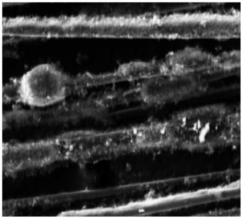
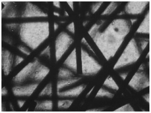
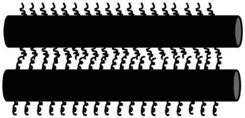

Image

  • Thermoplastic thermistor composite material with positive temperature coefficient and preparation method thereof
  • Thermoplastic thermistor composite material with positive temperature coefficient and preparation method thereof
  • Thermoplastic thermistor composite material with positive temperature coefficient and preparation method thereof

Examples


Embodiment 1

[0048] A positive temperature coefficient thermoplastic thermistor composite material, by weight percentage, comprising the following components:

[0049]

[0050] A positive temperature coefficient thermoplastic thermistor composite material is prepared by the following steps:

[0051] (1) Mix the carbon fiber powder with carbon nanotubes grown on the surface and KH-550 evenly, and dry to obtain a mixture A; the drying temperature is 50° C., and the drying time is 60 minutes;

[0052] (2) The thermoplastic polymer material and the ultra-high molecular weight polyethylene are mechanically mixed with the mixture A at room temperature to obtain the mixture B;

[0053] (3) mix mixture B with antioxidant 1010, UV-P, and naphthenic oil at room temperature and extrude in a twin-screw extruder, cool, dry and granulate to obtain a thermoplastic thermistor composite material; The cooling temperature was 30°C.

Embodiment 2

[0055] A positive temperature coefficient thermoplastic thermistor composite material, by weight percentage, comprising the following components:

[0056]

[0057]

[0058] A positive temperature coefficient thermoplastic thermistor composite material is prepared by the following steps:

[0059] (1) Mix the carbon fiber powder with carbon nanotubes grown on the surface and KH560 evenly, and dry to obtain the mixture A; the drying temperature is 100° C., and the drying time is 10 minutes;

[0060] (2) The thermoplastic polymer material and the ultra-high molecular weight polyethylene are mechanically mixed with the mixture A at room temperature to obtain the mixture B;

[0061] (3) mix mixture B with antioxidant 168, UV-326, and naphthenic oil at room temperature and extrude in a twin-screw extruder, cool, dry and granulate to obtain a thermoplastic thermistor composite material; The cooling temperature was 5°C.

Embodiment 3

[0063] A positive temperature coefficient thermoplastic thermistor composite material, by weight percentage, comprising the following components:

[0064]

[0065] A positive temperature coefficient thermoplastic thermistor composite material is prepared by the following steps:

[0066] (1) Mix carbon fiber powder with carbon nanotubes grown on the surface and KH570 evenly, and dry to obtain mixture A; the drying temperature is 90° C., and the drying time is 50 minutes;

[0067] (2) The thermoplastic polymer material and the ultra-high molecular weight polyethylene are mechanically mixed with the mixture A at room temperature to obtain the mixture B;

[0068] (3) mix mixture B with antioxidant 264, UV-531, and naphthenic oil at room temperature and extrude in a twin-screw extruder, cool, dry and granulate to obtain a thermoplastic thermistor composite material; The cooling temperature was 20°C.


PUM


Abstract

The invention discloses a thermoplastic thermistor composite material with a positive temperature coefficient and a preparation method thereof. The composite material is prepared from, by weight, 60-90% of a thermoplastic polymer material, 5-30% of ultrahigh molecular weight polyethylene, 1-30% of a conductive filler, 0.1-2% of a coupling reagent, 0.05-1.5% of an antioxidant, 0.05-1.5% of an ultraviolet absorber and 0.01-1.0% of naphthenic oil. The thermistor composite material has low electrical resistivity, the high positive temperature coefficient (PTC) and no negative temperature coefficient (NTC) effect.

Description

technical field [0001] The invention relates to the field of thermistors, in particular to a positive temperature coefficient thermoplastic thermistor composite material and a preparation method thereof. Background technique [0002] A positive temperature coefficient thermistor is a phenomenon in which its resistance value rises sharply with an increase in temperature. Positive temperature coefficient thermistors mainly use polymer composite materials with positive temperature coefficients, and their performance is mainly limited by the properties of polymer composite materials with positive temperature coefficients. Thermistors can be divided into positive temperature coefficient thermistors and negative temperature coefficient thermistors, the latter is not allowed to occur in the application of overcurrent protection. [0003] Positive temperature coefficient thermistors made of polymer resin as a matrix and filled with conductive fillers have been widely used in circui...

Claims


Application Information

Patent Timeline
IPC IPC(8): C08L101/00C08L23/06C08K13/06C08K9/02C08K7/06H01C7/02D06M11/74D06M101/40
CPCC08K2201/001C08L101/00C08L2205/03C08L2207/068D06M11/74D06M2101/40H01C7/027C08L23/06C08K13/06C08K9/02C08K7/06
Inventor 王可徐梦雪王悦辉
Owner UNIV OF ELECTRONICS SCI & TECH OF CHINA ZHONGSHAN INST
Learn More