Electroreduction CO2 device and method
A CO2, membrane electrode technology, applied in the field of electrochemistry, can solve the problems of the difficulty of large-scale industrial application of the dual electrolyte solution feeding mode, the difficulty of liquid mass transfer inside the solubility electrode, and the high requirements for anti-corrosion of pipeline equipment, so as to broaden the practical application of the process. performance, good economic and social benefits, and low equipment requirements
- Summary
- Abstract
- Description
- Claims
- Application Information
AI Technical Summary
Problems solved by technology
Method used
Image

Examples
Embodiment 1
[0061] The diaphragm R103 of the membrane electrode in the device of this embodiment is an anion exchange membrane, and the two sides of the diaphragm are respectively spray-coated with a cathode catalyst composed of nano-silver powder and carbon powder and an Ir black anode catalyst. The effective active area of the electrochemical reactor membrane electrode is 2500cm 2 .
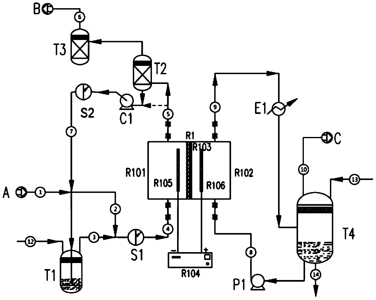
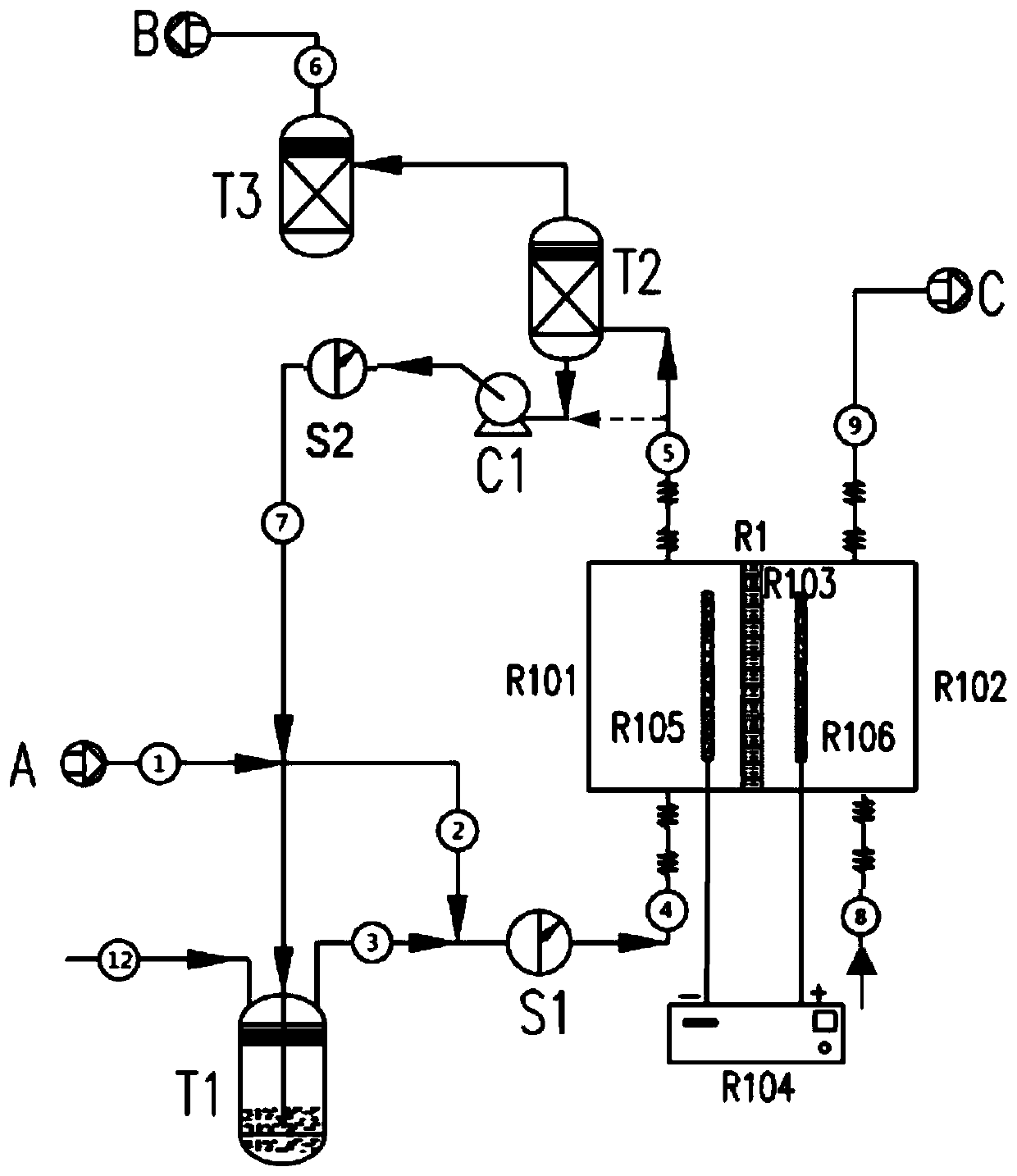
[0062] Such as figure 1 As shown, electroreduction of CO 2 The device includes electrochemical reaction unit R1 (including R101 cathode chamber, anode chamber R102; diaphragm 103, cathode electrode R105, anode electrode R106), cathode humidification tank T1, cathode drying tank T2, synthesis gas separator T3, anode tank T4, gas Circulation pump C1, humidity control controller S1, humidity meter S2, heat exchanger E1, anode circulation pump P1, main intake pipeline 1, first CO 2 Intake line 2, second CO 2 Intake pipeline 3, cathode inlet pipeline 4, cathode gas outlet pipeline 5, product synthesis gas...
Embodiment 2
[0069] This example uses figure 1 In the shown device, the diaphragm R103 is a cation exchange membrane, and the two sides of the diaphragm are respectively sprayed with a cathode catalyst composed of nano-silver powder and carbon powder and an Ir black anode catalyst. The effective active area of the electrochemical reactor membrane electrode is 2500cm 2 .
[0070] The process of preparing synthesis gas by device operation is as follows:
[0071] Use dry or wet CO 2 Gas A is used as the gas source, and the pre-treatment of A is the same as in Example 1, and the relative humidity of the feed gas is 60%. Also pass pure liquid water into the anode chamber R102 in the same manner as in Example 1. The electrochemical reactor R1 is energized by the DC power supply R104, and the pure water releases the anode product C(O 2 ). o 2 Return to the anode tank T4 through the first anode outlet line 9, and then be discharged through the second anode outlet line 10. CO 2 and H 2 ...
Embodiment 3
[0076] This example uses figure 1 The device shown, the diaphragm R103 is the same as that in Example 1. The two sides of the diaphragm are respectively sprayed with a cathode catalyst composed of nano-silver powder and carbon powder and an Ir black anode catalyst. The effective active area of the electrochemical reactor membrane electrode is 2500cm 2 .
[0077] Use dry or wet CO 2 Gas A is used as the gas source, and the pretreatment of A is the same as that in Example 1.
[0078] A potassium bicarbonate solution with a molar concentration of 0.02 mol / L was added to the anode tank T4 instead of liquid water, and the other steps were the same as in Example 1. During the operation of the device, there is no need to supplement potassium bicarbonate solution to the anode tank T4, and an appropriate amount of pure water can be supplemented through the anode water replenishment pipeline 13 depending on the situation. The relative humidity of the intake air at the R101 feed i...
PUM
 Abstract
Description
Claims
Application Information
 - R&D
- Intellectual Property
- Life Sciences
- Materials
- Tech Scout
- Unparalleled Data Quality
- Higher Quality Content
- 60% Fewer Hallucinations
Browse by: Latest US Patents, China's latest patents, Technical Efficacy Thesaurus, Application Domain, Technology Topic, Popular Technical Reports.
© 2025 PatSnap. All rights reserved.Legal|Privacy policy|Modern Slavery Act Transparency Statement|Sitemap|About US| Contact US: help@patsnap.com