

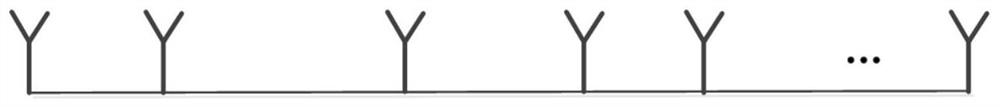
A Sparse Linear Array Antenna
A linear array and sparse technology, applied to antennas, antenna arrays, devices for manufacturing antenna arrays, etc., can solve the problem of array element location and optimal setting of array element excitation, limited fixed grid division, etc., to save the number of array elements , the effect of reducing the mismatch error
- Summary
- Abstract
- Description
- Claims
- Application Information
AI Technical Summary
Problems solved by technology
Method used
Image

Examples
example 1
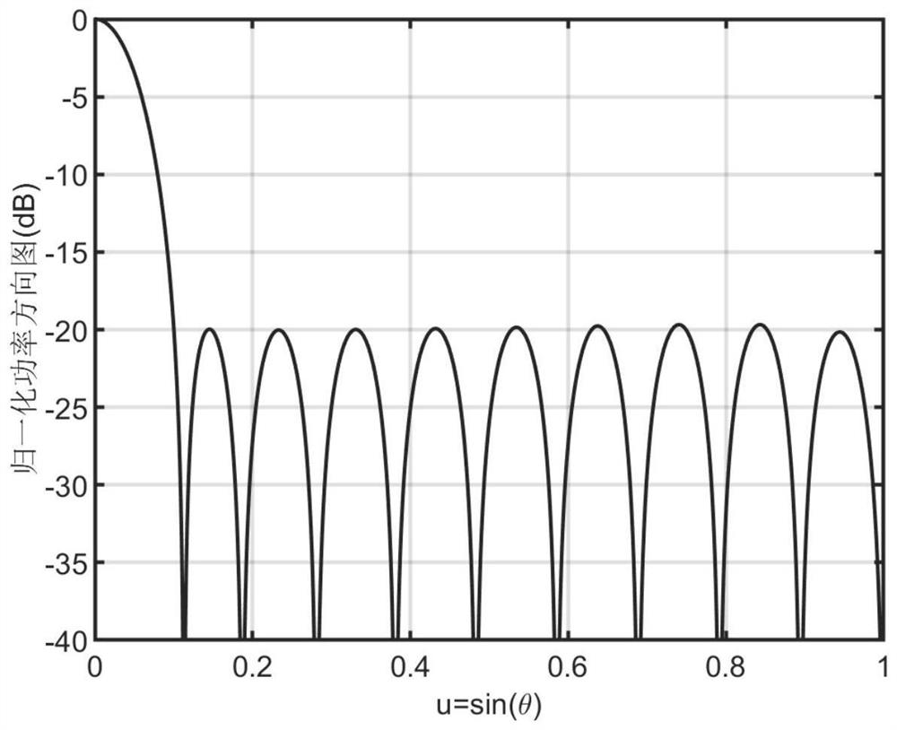
[0098] In Example 1, a sparse linear array is synthesized within a given array aperture L=9.5λ to realize a Chebyshev pattern with a sidelobe level of -20dB. Existing studies have shown that if a uniform full array with an adjacent element interval of 0.5λ is used, 20 array elements are needed; if the pattern realized by the full array is used as a reference pattern, considering the symmetrical structure of the array, here only The positive semi-axis of the array aperture is divided into grids, and the sparse linear array antenna is designed using the traditional compressed sensing method. Under the premise that the initial number of grids is 951, 13 array elements are required to achieve the desired reference pattern. Using the sparse linear array antenna proposed by the present invention, when the initial number of grids is only 23, only 12 array elements are needed to achieve the same radiation characteristics, and the integrated pattern is as follows image 3 As shown, it ...
example 2
[0101] Example 2 Design a sparse linear array within a given array aperture L=9.5λ to achieve as image 3 The cosecant beam pattern shown. Utilize the method of the present invention, set the initial array element number to be 37, simulation result shows, the antenna of the present invention design only needs 15 array elements, and the comparison result of pattern is as follows Figure 4 As shown, it can be seen that the sparse linear array antenna of the present invention has achieved the desired radiation characteristics, and the corresponding array element positions and excitations are shown in Table 2. From this example, it can be seen that the antenna of the present invention can be any beam-shaped Sparse linear array antenna.
[0102] Table 2
[0103] Array element number Array element position (λ) Array element excitation Array element number Array element position (λ) Array element excitation 1 0 0.1336-j0.1031 9 5.3580 -0.6477+j0.5463 ...
PUM
 Abstract
Description
Claims
Application Information