Evaporation device and evaporation system for high-speed evaporation with multiple physical fields
An evaporation device and physical field technology, applied in seawater treatment, water/sewage treatment, heating water/sewage treatment, etc., can solve the problems of low evaporation rate, large footprint, poor weather resistance, etc., to achieve no secondary pollution, reduce Heat loss and good water absorption
- Summary
- Abstract
- Description
- Claims
- Application Information
AI Technical Summary
Problems solved by technology
Method used
Image


Examples
Embodiment 1
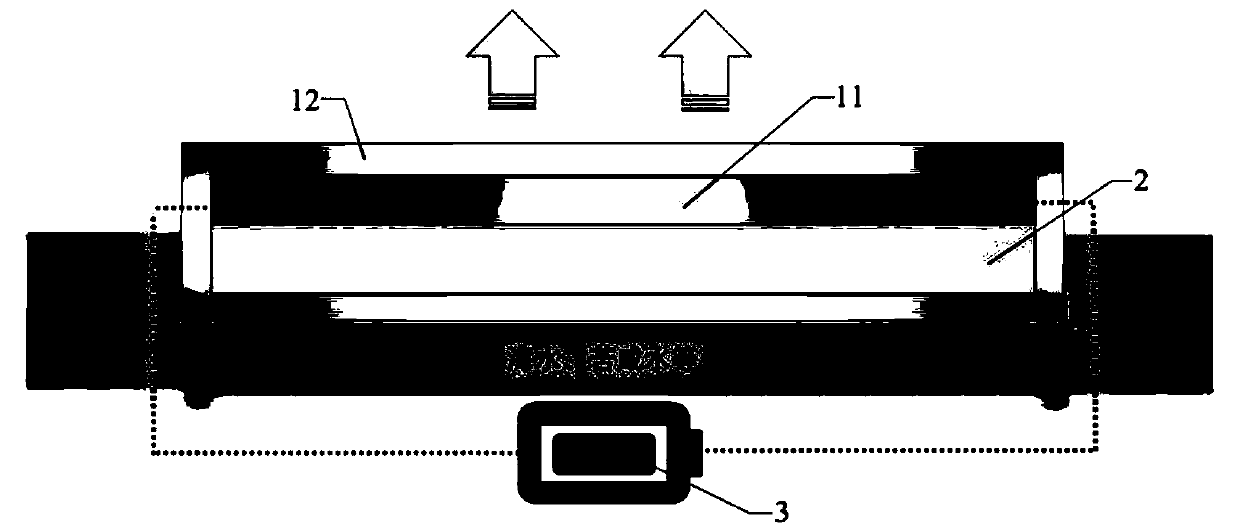
[0037] see figure 1 and figure 2 As shown, the embodiment of the present invention provides an evaporation device that utilizes various physical fields for high-speed evaporation, including an evaporation layer, a hydrophobic heat insulating layer 2, and a power supply device 3. The evaporation layer is configured to have heating and hydrophilic properties, and the evaporation The layer is used to extend into the water to be treated, the hydrophobic heat insulating layer 2 is arranged at the bottom of the evaporation layer, the power supply device 3 is connected with the evaporation layer, further, the evaporation layer includes a heating layer 11 and a hydrophilic layer 12, and the heating layer 11 is used to transfer electric energy And / or light energy is converted into thermal energy, the hydrophilic layer 12 is attached to one side of the heating layer 11, the hydrophilic layer 12 is used to extend into the water to be treated, and conduct the water to be treated to a pos...
Embodiment 2
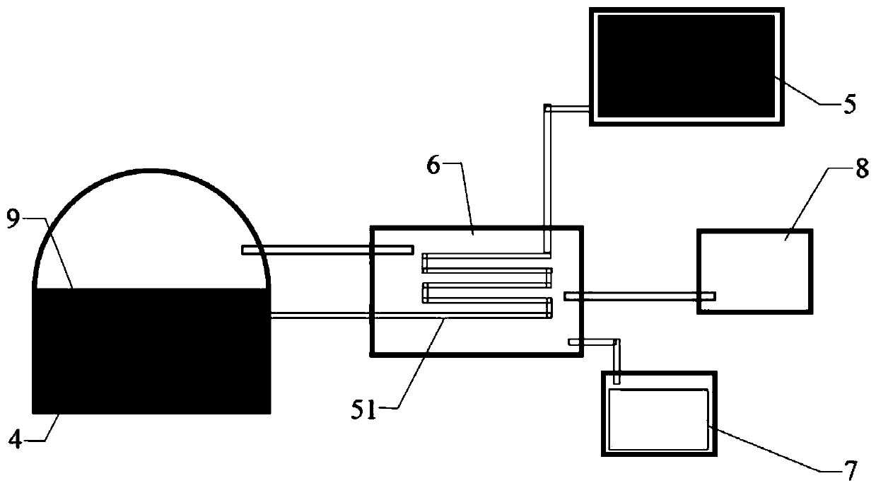
[0044] see image 3 As shown, the embodiment of the present invention provides an evaporation system, including:
[0045] The evaporation chamber 4 is provided with the evaporation device 9 and the light-transmitting area 31 of the above-mentioned embodiment 1 in the evaporation chamber 4, the light-transmitting area and the evaporation device 9 are arranged directly, and the light-transmitting area is used to transmit sunlight;
[0046] The first water storage tank 5, the first water storage tank 5 communicates with the evaporation chamber 4, and the first water storage tank 5 is used to store water to be treated;
[0047] Condensation heat exchange chamber 6, the condensation heat exchange chamber 6 communicates with the evaporation chamber 4;
[0048] The second water storage tank 7, the second water storage tank 7 communicates with the bottom of the condensation heat exchange chamber 6;
[0049] Negative pressure generating device 8, the negative pressure generating devi...
Embodiment 3
[0053] On the basis of Example 2, in this example, the heating layer 11 is carbon cloth, the hydrophilic layer 12 is a hydrophilic fiber cloth, and the hydrophobic heat insulating layer 2 is polystyrene foam, wherein the hydrophilic fiber cloth covers Hydrophobic and heat-insulating polystyrene foam, the two ends of the carbon cloth are connected to the power supply device 3 with platinum electrodes, the heating part of the carbon cloth is in close contact with the hydrophilic fiber cloth by bonding, and the carbon cloth is kept facing upwards. It is placed in seawater to be treated.
[0054] When seawater is desalinated through the evaporation system, the normal light AM 1.5G, that is, the radiation intensity is 1kW / m 2 Under light conditions, no electric field and negative pressure (the power supply device 3 does not supply power, and the negative pressure generating device 8 has no effect), the desalination rate of seawater can reach 1.5kg m -2 h -1 ;In the normal light A...
PUM
| Property | Measurement | Unit |
|---|---|---|
| Resistance | aaaaa | aaaaa |
Abstract
Description
Claims
Application Information
 - Generate Ideas
- Intellectual Property
- Life Sciences
- Materials
- Tech Scout
- Unparalleled Data Quality
- Higher Quality Content
- 60% Fewer Hallucinations
Browse by: Latest US Patents, China's latest patents, Technical Efficacy Thesaurus, Application Domain, Technology Topic, Popular Technical Reports.
© 2025 PatSnap. All rights reserved.Legal|Privacy policy|Modern Slavery Act Transparency Statement|Sitemap|About US| Contact US: help@patsnap.com