Wave energy power generation device

A power generation device and wave energy technology, which is applied in ocean energy power generation, hydropower generation, engine components, etc., can solve problems such as easy corrosion of parts, and achieve the effect of improving efficiency, avoiding sealing requirements, and avoiding manual cleaning.

Inactive Publication Date: 2019-10-25
HUBEI UNIV
View PDF1 Cites 1 Cited by
  • Summary
  • Abstract
  • Description
  • Claims
  • Application Information

AI Technical Summary

Problems solved by technology

A wave power generation device and a wave power generation system in the above-mentioned patents have the following disadvantages: the flow of seawater drives ...

Method used


Image

  • Wave energy power generation device
  • Wave energy power generation device
  • Wave energy power generation device

Examples


Embodiment 1

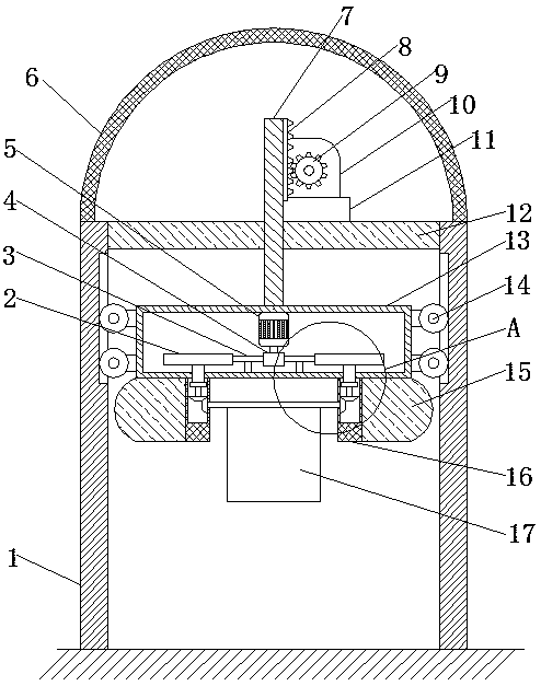
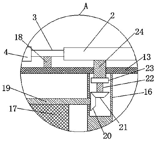
[0028] refer to Figure 1-4 , a wave energy power generation device, including two support plates 1, a mobile body 13 is arranged between the two support plates 1, a cavity is opened in the middle of the mobile body 13, and two fixed bodies are welded at the bottom of the mobile body 13 16. One side of the two fixed bodies 16 is provided with a float 15, the float 15 can make the moving body 13 above the sea water, and does not contact with the sea water, and a rotating rod 19 is arranged between the two fixed bodies 16, and the rotating rod 19 The bottom end is welded with a rotating plate 17, and most of the bottom ends of the rotating plate 17 are in the interior of the seawater. slot, the fixed body 16 is provided with a second rotating shaft 22 and a third rotating shaft 24 at the first groove, a ratchet 23 is arranged between the second rotating shaft 22 and the third rotating shaft 24, and the bottom end of the moving body 13 is opened There are two first circular thro...

Embodiment 2

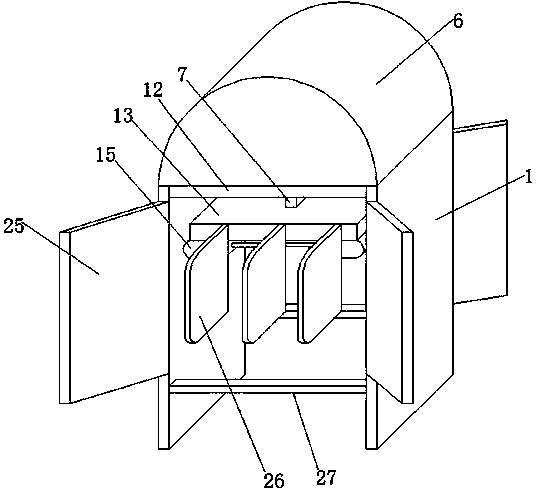
[0039] refer to Figure 5 , a wave energy generating device, in order to reduce the damage of the device to the marine ecology, both sides of the rectifying plate 26 are provided with rigid ropes 28, and the other end of the rigid rope 28 is provided with a metal ball 29, and the seawater moves back and forth. During the process, the metal ball 29 will be driven to collide with the rectifying plate 26 to generate noise, drive fish away, and prevent fish from entering the interior of the device.

[0040] During use, the sea waves will move back and forth, and when they move to one side, the sea water will pass through the gradually narrowed sea water inlet of the collecting plate 25, accelerate the flow of sea water, provide greater kinetic energy to make the rotating plate 17 rotate, and when the sea waves make the rotating plate 17 rotate, The angle between the rotating plate 17 and the thrust of the sea wave decreases, and the thrust on the rotating plate 17 will gradually d...


PUM


Abstract

The invention belongs to the technical field of wave power generation, in particular to a wave energy power generation device. Aiming at the technical problem that wave energy power generation devicesare in contact with seawater and are liable to be corroded, according to the following scheme, the wave energy power generation device comprises two support plates; a movable body is arranged betweenthe two support plates; the middle of the movable body is provided with a cavity; two fixed bodies are welded to the bottom end of the movable body; one sides of the two fixed bodies are provided with floats; a rotating rod is arranged between the two fixed bodies; a rotating plate is welded to the bottom end of the rotating rod; and the top ends of the two fixed bodies are provided with first grooves. Through the floats, the effect that a device main body is always located above seawater can be ensured, corrosion of seawater and the sealing requirement of the device are avoided, a first generator can rotate and generate power through the rotating plate, a movable plate can drive a second generator to generate power, the second generator provides protection for the support plates, thus, the support plates are not corroded by seawater due to electron loss, a metal ball impacts a current plate, and fish is driven.

Description

technical field [0001] The invention relates to the technical field of ocean wave power generation, in particular to an ocean wave power generation device. Background technique [0002] The waves in the ocean have very powerful energy, and the waves are mainly formed by the blowing of the wind. They are a very large renewable energy source. However, seawater is erosive. Generally, power generation through seawater is driven by the flow of seawater. The water turbine rotates to generate electricity, and the sealing performance of the device must be ensured during use, and corrosion resistance must also be ensured. [0003] After searching, the Chinese patent application number is 201811157125.X, which discloses a wave power generation device and a wave power generation system, involving the technical field of wave power generation. The wave power generation device includes: a plurality of buoyant cylinders, a plurality of hydraulic cylinders, and a water turbine carrying a g...

Claims


Application Information

Patent Timeline
IPC IPC(8): F03B13/22F03B13/18F03B11/00A01M29/16
CPCA01M29/16F03B11/00F03B13/186F03B13/22F05B2220/706Y02E10/20Y02E10/30
Inventor 王乐婷王永玲胡洋
Owner HUBEI UNIV
Why Eureka
Try Eureka