Wavelength-combined laser device

A laser and laser technology, applied in the direction of lasers, laser components, semiconductor lasers, etc., can solve problems such as crosstalk, beam quality and photoelectric conversion efficiency reduction, and achieve high beam quality and high photoelectric conversion efficiency.

Active Publication Date: 2019-10-25
MITSUBISHI ELECTRIC CORP
View PDF13 Cites 0 Cited by
  • Summary
  • Abstract
  • Description
  • Claims
  • Application Information

AI Technical Summary

Problems solved by technology

[0005] In wavelength-coupled resonators, cross-coupling oscillations that degrade beam quality and photoelectric conversion efficiency, so-called crosstalk, are prone to occur.

Method used


Image

  • Wavelength-combined laser device
  • Wavelength-combined laser device
  • Wavelength-combined laser device

Examples


Embodiment approach 1

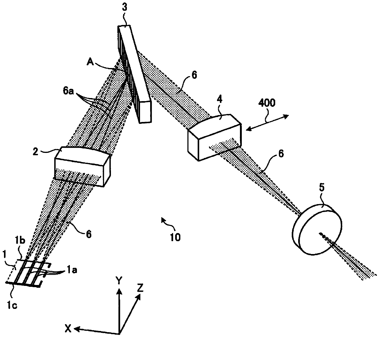
[0030] figure 1 It is a diagram showing the configuration of the wavelength-coupled laser device 10 according to Embodiment 1 of the present invention. The wavelength-coupled laser device 10 has: an LD bar 1 which is a semiconductor laser provided with a plurality of light-emitting portions, ie, a light-emitting layer 1 a ; a light-condensing element 2 ; a wavelength coupling element 3 ; a cross-coupling suppression optical system 4 ; and a partial mirror 5 . A specific example of each of the condensing element 2 and the cross-coupling suppression optical system 4 is a lens. A specific example of the wavelength coupling element 3 is a diffraction grating.

[0031] About 10 to 50 light emitting layers 1 a are provided in the LD bar 1 , and are arranged at equal intervals in the width direction of the LD bar 1 . The width direction of the LD bar 1 is the direction in which the wavelength coupling element 3 couples the laser light 6 , that is, the laser coupling direction. exi...

Embodiment approach 2

[0059] Figure 8 It is a diagram showing the configuration of a wavelength-coupled laser device 11 according to Embodiment 2 of the present invention. exist Figure 8 , labeled with figure 1 and Figure 4 Structural elements with the same reference numbers are the same. The wavelength-coupled laser device 11 shown in the second embodiment includes a beam shaping element 7 . That is, the LD bar 1 of the wavelength-coupled laser device 11 has the beam shaping element 7 facing the output end face 1b. Before the plurality of laser beams 6 emitted as diverging light from the arrayed light emitting layers 1a arranged at equal intervals in the X direction in the width direction of the LD bar 1 coincide with each other, the beam shaping element 7 pairs the laser beams 6 emitted from the LD bar 1 with each other. The laser beam 6 is collimated to suppress the divergence angle. The plurality of laser beams 6 collimated by the beam shaping element 7 enter the wavelength coupling el...

Embodiment approach 3

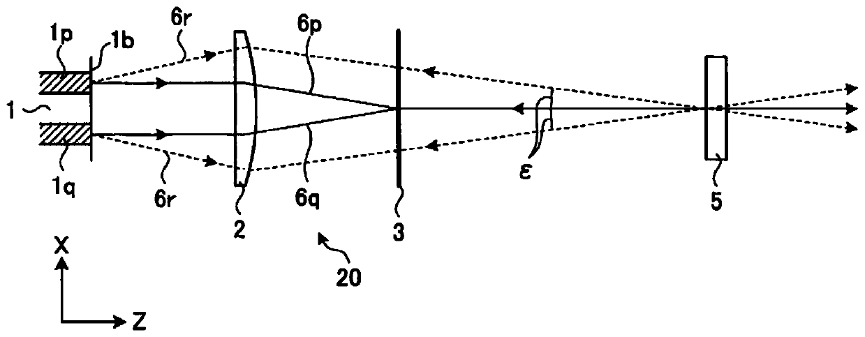
[0070] Figure 11 It is a diagram explaining how the beam quality deteriorates in the wavelength-coupled laser device 10 according to the first embodiment. The cross-coupling oscillation can be suppressed by the cross-coupling suppression optical system 4 included in the wavelength-coupled laser device 10 according to the first embodiment and the wavelength-coupled laser device 11 according to the second embodiment. Lower beam quality degraded.

[0071] Figure 11 It is a diagram for explaining the reduction in beam quality caused by the cross-coupling suppressing optical system 4 in the wavelength-coupled laser device 10 according to the first embodiment. Figure 11 For simplification, only three light emitting layers 1a are drawn. Considering only the laser light 6 emitted from the luminescent layer 1a in the middle, the solid line is the chief ray 6a, and the dotted line is the divergent light representing the imaging of the exit end surface 1b on the partial reflection ...


PUM


Abstract

A wavelength-combined laser device (10) is provided with: a semiconductor laser which emits, from emitting end surfaces (1b) of a plurality of light-emitting parts arranged in the laser beam combination direction, a plurality of laser beams (6) in the optical axis direction perpendicular to the laser beam combination direction; a wavelength combining element (3) which combines the plurality of laser beams in the laser beam combination direction and emits the combined laser beams as a single laser beam; a cross-coupling suppression optical system (4) which has positive power in the laser beam combination direction perpendicular to the optical axis of the single laser beam output from the wavelength combining element; and a partial reflecting mirror (5) which reflects the single laser beam that has passed through the cross-coupling suppression optical system and transmits and outputs the laser beam, wherein, in the plane formed by the optical axis and the laser beam combination direction, the cross-coupling suppression optical system is disposed so that images of the emitting end surfaces are formed on the partial reflective mirror by connecting, in a conjugate manner, the emitting end surfaces and the partial reflective mirror.

Description

technical field [0001] The present invention relates to a wavelength-coupled laser device that combines laser light emitted from a plurality of light emitting parts of a semiconductor laser. Background technique [0002] As an example of a laser oscillator that combines light emitted from many semiconductor laser diodes (Laser Diode: LD) (hereinafter referred to as LD light), there is a wavelength coupling type resonator using a diffraction grating as a wavelength coupling element. [0003] In recent years, in processes such as cutting and welding of metals, LD light having a wavelength of 900 nm or 1000 nm and having a high photoelectric conversion efficiency has been directly used. However, in these applications, the focal power of a single LD light, i.e., the light emitted from one light emitting layer of a semiconductor element, that is, the active layer stripe, is limited. Therefore, in order to obtain laser light with high power, light from a plurality of light emittin...

Claims


Application Information

Patent Timeline
Patent Type & Authority Applications(China)
IPC IPC(8): H01S5/14G02B3/06G02B5/18H01S5/022
CPCG02B3/06G02B5/18H01S5/141H01S5/4012H01S5/4062H01S5/4087H01S3/08054H01S3/08059H01S5/143H01S5/4025H01S5/4031
Inventor 小林信高桂智毅森田大嗣西前顺一京藤友博
Owner MITSUBISHI ELECTRIC CORP
Why Eureka
Try Eureka