
Method for adaptively expanding dynamic range of photomultiplier

A photomultiplier tube and dynamic range technology, which is applied in the direction of electron multiplier dynode, electron multiplier detailed information, dynode, etc., can solve the problems of excessive total number of electrons, restricting the dynamic range of photomultiplier tube, etc., and achieve the expansion of dynamic range Effect

Active Publication Date: 2019-10-29
XI'AN INST OF OPTICS & FINE MECHANICS - CHINESE ACAD OF SCI
View PDF10 Cites 4 Cited by
  • Summary
  • Abstract
  • Description
  • Claims
  • Application Information

AI Technical Summary

Problems solved by technology

[0006] In order to solve the problem that the current general-purpose photomultiplier tube restricts the dynamic range of the photomultiplier tube due to electron multiplication and the total number of electrons in the transmission process is too large, the present invention provides a method for adaptively expanding the dynamic range of the photomultiplier tube

Method used


Image

  • Method for adaptively expanding dynamic range of photomultiplier
  • Method for adaptively expanding dynamic range of photomultiplier
  • Method for adaptively expanding dynamic range of photomultiplier

Examples


Embodiment Construction

[0052] The present invention will be described in detail below in conjunction with the accompanying drawings.

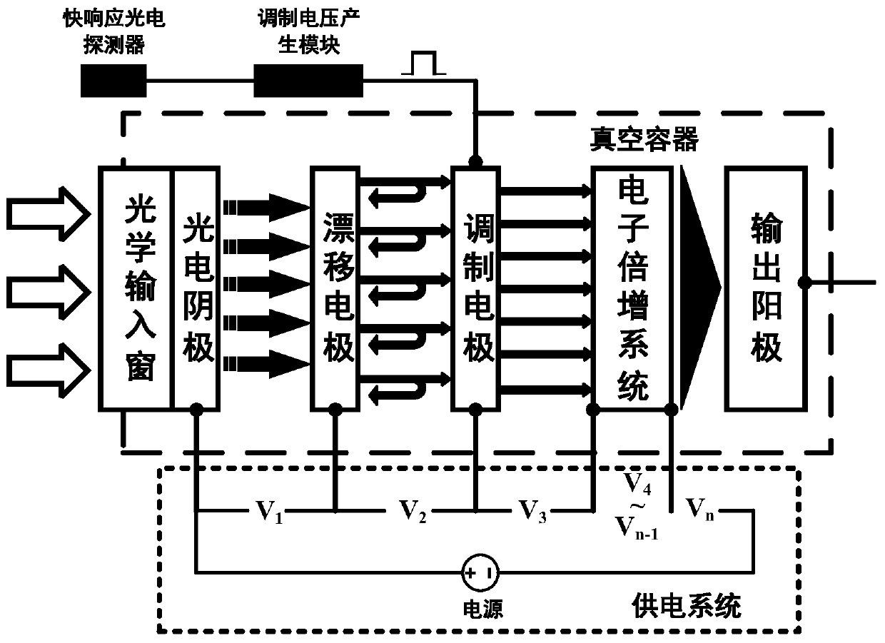
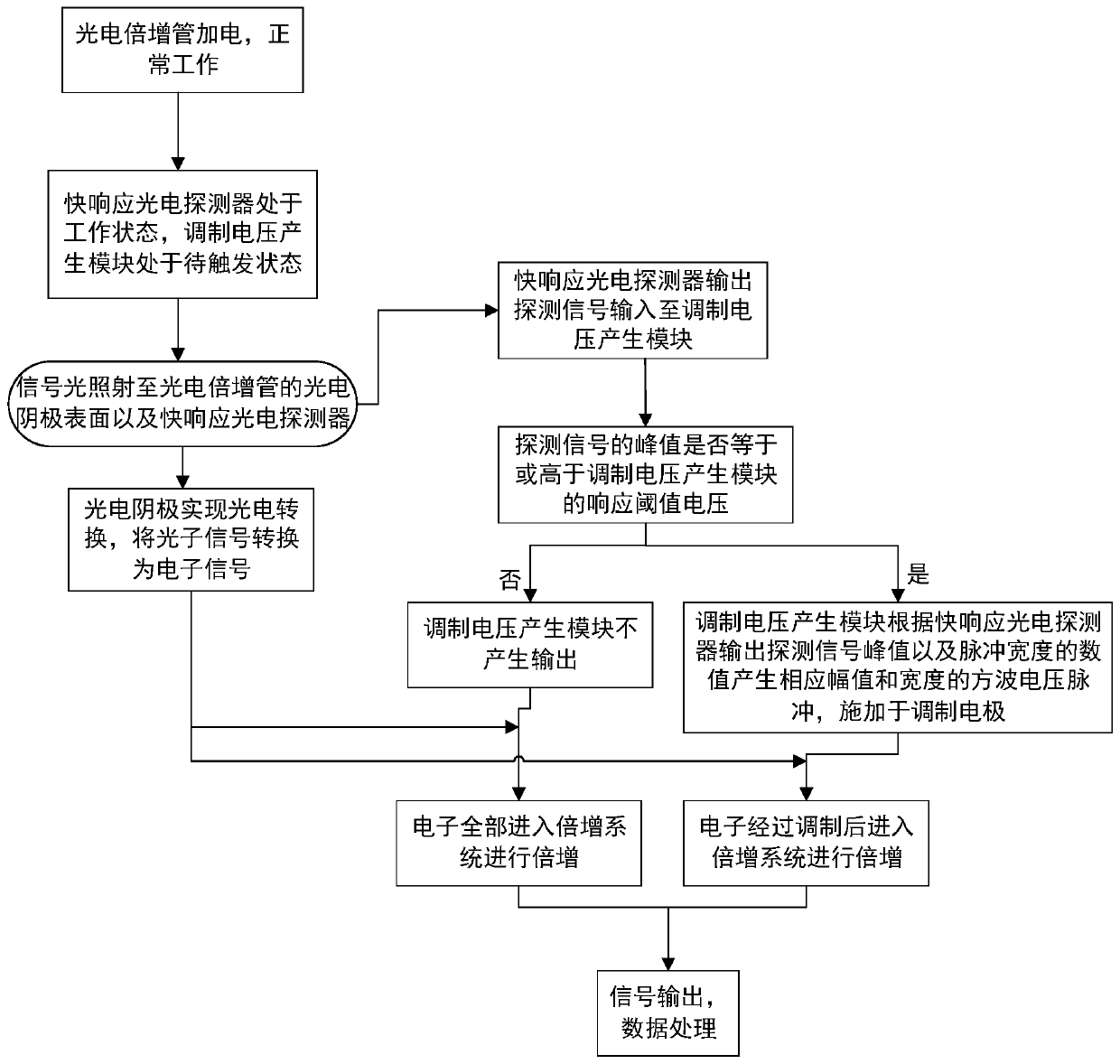
[0053] Such as figure 1 , figure 2 As shown, the method for adaptively extending the dynamic range of the photomultiplier tube provided by the present invention comprises the following steps:

[0054] 1) if figure 1 As shown, a drift electrode, a modulation electrode, and a drift electrode power supply electrode and a modulation electrode power supply electrode for supplying voltage to the drift electrode and the modulation electrode are set between the focusing electrode of the photomultiplier tube and the electron multiplication system, and the drift electrode and the modulation electrode are 1. The center of the electron multiplier system and the anode is coaxial (if not coaxial, the time characteristic of the photomultiplier tube will be reduced, or the adjustment function of the photomultiplier tube will be affected); and the response time is set outside the ...


PUM


Abstract

The invention provides a method for adaptively expanding the dynamic range of a photomultiplier in order to solve the problem that the dynamic range of an existing universal photomultiplier is limiteddue to the fact that the total number of electrons is too large in the electron multiplication and transmission process. The number of electrons entering the electron multiplication system is adaptively adjusted according to the intensity of the detection light, so that the electron multiplication system is in a linear output working state, the dynamic range of the photomultiplier for the intensity of the detection light is expanded, and the range can be increased by more than 10 times of the original numerical value.

Description

technical field [0001] The invention relates to a method for self-adaptively expanding the dynamic range of a photomultiplier tube according to the change of the detected light intensity. Background technique [0002] Photomultiplier tube (referred to as PMT) is an electric vacuum photodetection device, mainly composed of photocathode, electron multiplication system and anode, the main function is to convert the weak optical signal emitted by the detection target into a space electron beam signal, and to The electron beam signal is amplified and output to realize the function of target detection. [0003] This year, the photomultiplier tube has a good application prospect in the new field of underwater wireless optical communication. Since the blue-green light of the "seawater transmission light port" is generally used as the communication carrier for underwater wireless optical communication, the detectors used are generally blue-green light-enhanced devices. [0004] For...

Claims


Application Information

Patent Timeline
IPC IPC(8): G06F17/50H01J43/04H01J43/06H01J43/10
CPCH01J43/10H01J43/04H01J43/06G06F30/30G06F30/367
Inventor 刘虎林温文龙吕沛徐向晏田进寿赛小锋韩彪何凯何建平王俊锋韦永林卢裕王兴陈萍高贵龙辛丽伟
Owner XI'AN INST OF OPTICS & FINE MECHANICS - CHINESE ACAD OF SCI
Learn More