Supercharge Your Innovation With Domain-Expert AI Agents!

Optical transmitter drive circuit based on 3-tap feed-forward equalization pre-emphasis

A technology for driving circuits and optical transmitters, applied in transmitter/receiver shaping networks, electromagnetic transmitters, baseband systems, etc., can solve problems such as large chip footprint, large chip area, and unsatisfactory equalization effect , to achieve the effects of small environmental changes, high transmission rate, and improved operation stability

Active Publication Date: 2022-02-18
TIANJIN UNIV
View PDF2 Cites 0 Cited by
  • Summary
  • Abstract
  • Description
  • Claims
  • Application Information

AI Technical Summary

Problems solved by technology

For example, the Southern Methodist University in the United States adopted a pre-emphasis technology combining source-level degeneration and peaking inductance to realize a 4×10Gb / s VCSEL drive array [1] , but the introduction of inductance makes the chip area too large; Fudan University and the Chinese Academy of Sciences used time continuity equalization, negative capacitance compensation, peaking inductance and feedforward equalization technology to design a 25Gb / s DFB drive circuit [2] , but the feed-forward equalization pre-emphasis only has 2 taps, the equalization effect is not ideal, and passive inductors are used in the circuit, and the chip occupies a large area

Method used


Image

  • Optical transmitter drive circuit based on 3-tap feed-forward equalization pre-emphasis
  • Optical transmitter drive circuit based on 3-tap feed-forward equalization pre-emphasis
  • Optical transmitter drive circuit based on 3-tap feed-forward equalization pre-emphasis

Examples


Embodiment 1

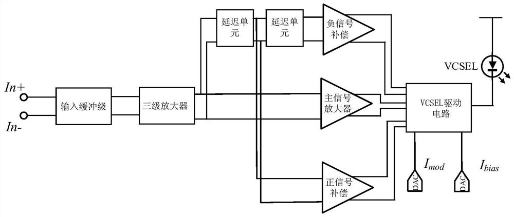
[0034] The optical transmitter driving circuit based on 3-tap feed-forward equalization pre-emphasis proposed in the embodiment of the present invention includes:

[0035] An input buffer stage that provides input impedance matching;

[0036] A three-stage amplifier that provides sufficient circuit gain;

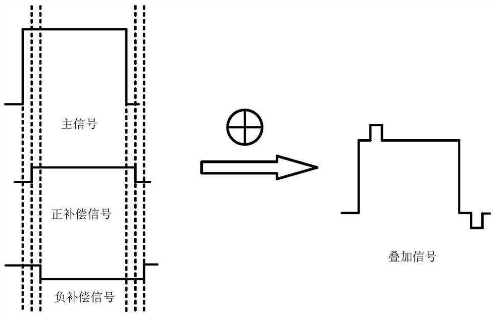
[0037] An equalizer based on feed-forward equalization technology (FFE), which is composed of three-way signal amplifiers and two delay units to pre-compensate the high-frequency loss of the transmitted signal;

[0038] A drive circuit is used to superimpose the balanced signal to obtain a compensated modulation current signal and provide a bias current signal at the same time.

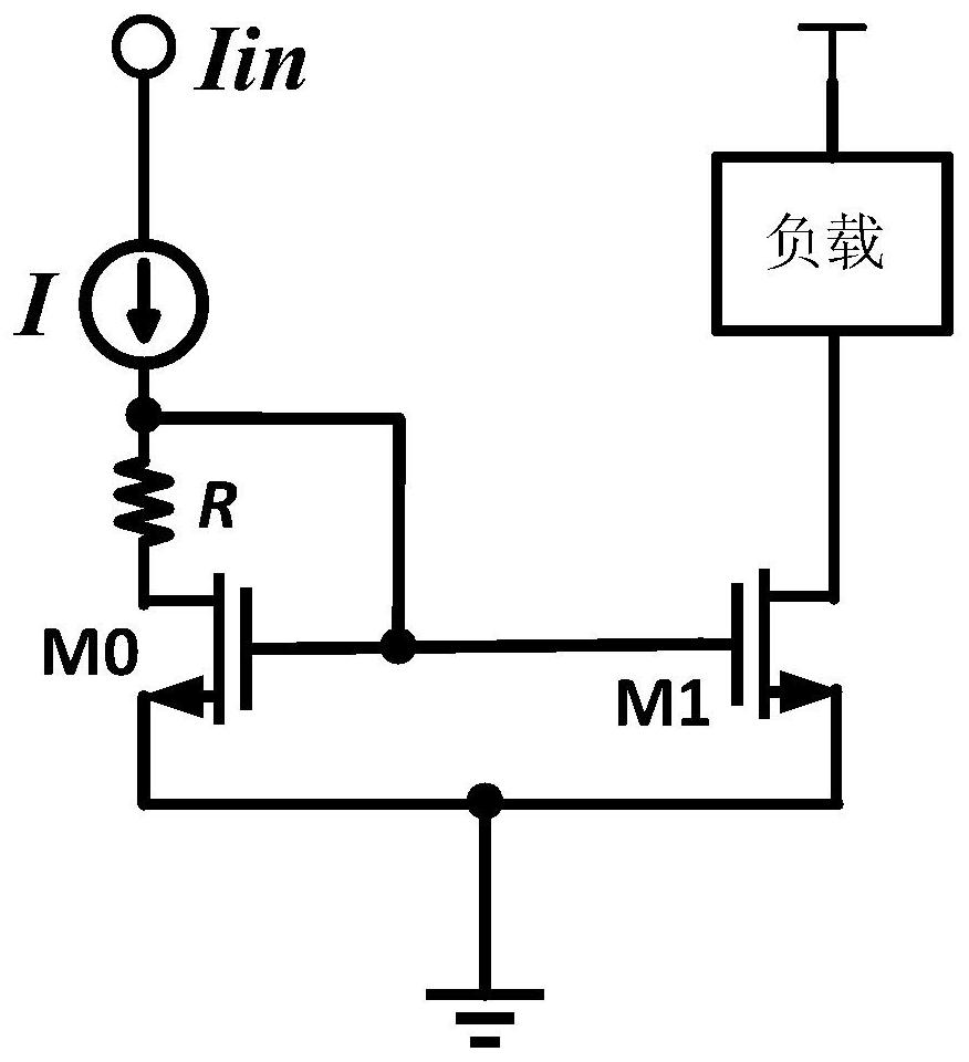
[0039] Due to manufacturing process deviations and environmental changes, the overall performance of the circuit will shift as the process corner changes.

[0040] In order to overcome this problem, the embodiment of the present invention introduces a current mirror structure that is not sensitive...

Embodiment 2

[0043] In the field of optical transmitters, the vertical cavity surface emitting laser (VCSEL) has excellent characteristics such as vertical surface emission, low threshold current, and low cost, and has become the preferred light source in the field of optical transmitters. Therefore, the optical transmitter driving circuit in the embodiment of the present invention uses a VCSEL laser as the emitting light source.

[0044] Due to non-ideal factors such as skin effect and dielectric loss, high-frequency signals will be distorted during transmission. Due to the low-pass characteristic of the conventional transmission medium, the high-frequency component of the signal transmitted to the receiving end will be seriously attenuated, which will affect the signal judgment and cause a bit error rate. The basic idea of ​​the pre-emphasis technology is to pre-compensate the high-frequency loss of the signal at the transmitting end, so that the high-frequency and low-frequency componen...


PUM


Abstract

The invention discloses an optical transmitter drive circuit based on 3-tap feedforward equalization pre-emphasis, the drive circuit includes: an input buffer stage, used to provide input impedance matching; a delay unit, realized in the form of multi-stage cascading, In addition, a variable capacitor is introduced to provide time delay; the delay unit, the main signal amplifier, the positive signal compensation, and the negative signal compensation are composed of a 3-tap feed-forward equalizer to compensate for the high-frequency loss of the signal; the VCSEL drive circuit converts the obtained signal Superposition, the modulation tail current and bias current are provided by the digital-to-analog converter. The present invention further improves the transmission rate of the optical transmitter, compensates the high-frequency loss of the signal, and improves the bandwidth of the transmitting circuit under the premise of ensuring a certain bit error rate of the optical fiber communication.

Description

technical field [0001] The invention relates to the field of high-speed optical fiber communication, in particular to an optical transmitter drive circuit based on 3-tap feed-forward equalization pre-emphasis. Background technique [0002] With the rapid development of communication technology, the information age has gradually evolved into the era of big data, artificial intelligence technology has shown excellent application prospects, and the popularity of wireless sensor networks has become more and more extensive. With the continuous promotion and popularization of applications, people have higher and higher requirements on the data capacity and rate of communication networks. The International Semiconductor Technology Roadmap points out that due to the avalanche increase in information generation and transmission, the performance of existing electrical interconnections can no longer meet the growth rate of chip performance and the requirements of communication system d...

Claims


Application Information

Patent Timeline
Patent Type & Authority Patents(China)
IPC IPC(8): H04B10/58H04L25/03
CPCH04B10/58H04L25/03343H04L2025/03471
Inventor 谢生石岱泉毛陆虹
Owner TIANJIN UNIV
Features
  • R&D
  • Intellectual Property
  • Life Sciences
  • Materials
  • Tech Scout
  • Unparalleled Data Quality
  • Higher Quality Content
  • 60% Fewer Hallucinations
Learn More