Power system structure of coaxial dual-rotor-wing unmanned aerial vehicle

A coaxial dual-rotor and system structure technology, applied in the field of aircraft, can solve the problems of low efficiency and poor stability, and achieve the effect of high efficiency, enhanced performance, and deceleration effect.

Active Publication Date: 2019-11-08
SICHUAN AEROSPACE ZHONGTIAN POWER EQUIP CO LTD
View PDF6 Cites 2 Cited by
  • Summary
  • Abstract
  • Description
  • Claims
  • Application Information

AI Technical Summary

Problems solved by technology

[0004] Based on the above problems, the present invention provides a coaxial dual-rotor UAV power system structure, which is used to solve the problems of low efficiency and poor stability of the existing coaxial dual-rotor UAV power system

Method used


Image

  • Power system structure of coaxial dual-rotor-wing unmanned aerial vehicle
  • Power system structure of coaxial dual-rotor-wing unmanned aerial vehicle
  • Power system structure of coaxial dual-rotor-wing unmanned aerial vehicle

Examples


Embodiment 1

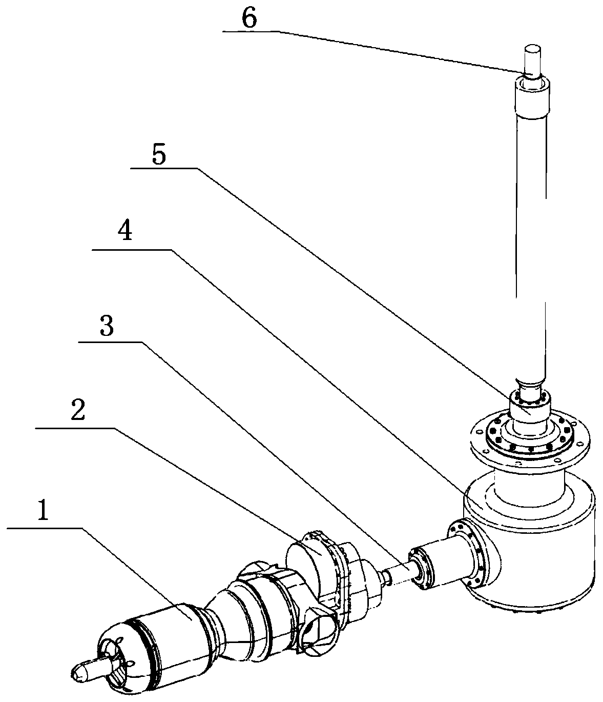
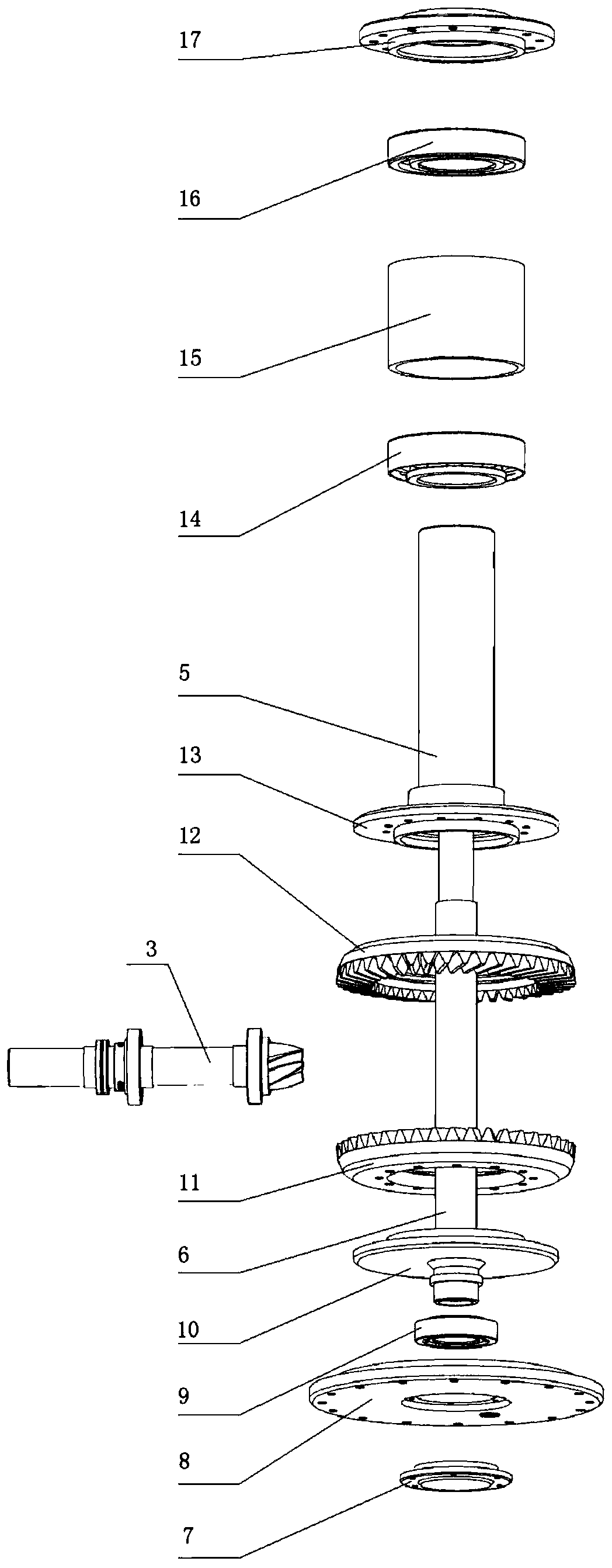
[0033] Such as Figure 1-6 As shown, a coaxial dual-rotor unmanned aerial vehicle power system structure includes a micro turboshaft engine 1, a main stage reducer 2 and a secondary reducer 4, and the main stage reducer 2 is connected to the free turbine of the micro turboshaft engine 1 , the output shaft of the primary reducer is connected to the input shaft of the secondary reducer 4, the primary reducer 2 includes a fuel lubrication system; the secondary reducer 4 includes an input shaft 3, an inner output shaft assembly and an outer output shaft assembly, The rotation directions of the inner output shaft assembly and the outer output shaft assembly are opposite, and the second-stage speed reducer 4 also includes a lubricating oil lubrication system.

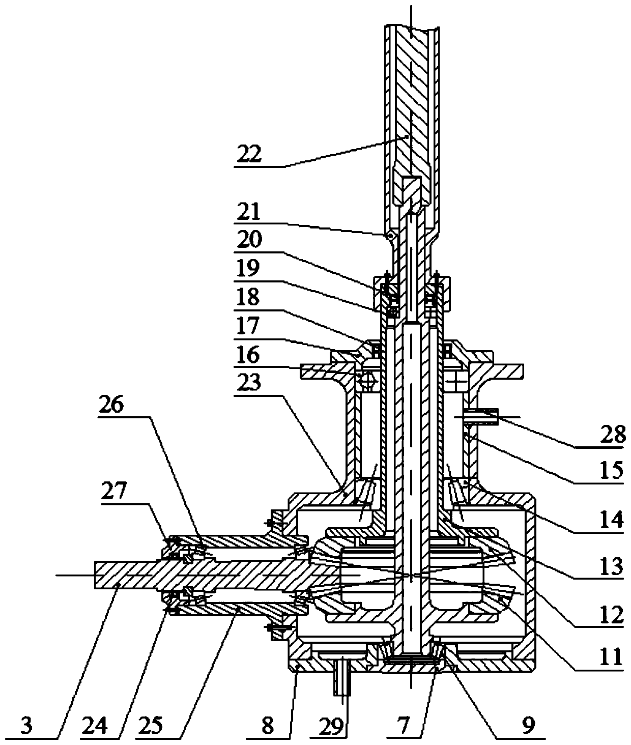
[0034] Preferably, the secondary reducer 4 includes a bearing housing 25 and a reducer housing 23 connected to each other, the input shaft 3 is installed in the bearing housing 25, and the input shaft 3 is perpendicular to th...

Embodiment 2

[0046] Such as Figure 5 As shown, on the basis of Embodiment 1, this embodiment provides a preferred form of the fuel lubrication system, that is, the lubrication system of the stage reducer 2 adopts fuel lubrication, and the fuel is stored in the fuel tank 32. Through the fuel pump 33, The fuel oil filter 34 enters the power turbine bearing 35 for cooling, and the fuel flowing out from the bearing bush 15 is divided into two paths, one part passes through the throttle valve 36 to cool the main stage reducer 2, and the other part is supplied to the gas generator, Participate in combustion in the combustion chamber, convert chemical energy into mechanical energy, and achieve the purpose of power output. The main stage reducer 2 adopts the fuel lubrication method, which not only realizes the cooling of the reducer, but also ensures that the high-temperature fuel output from the reducer participates in the combustion, thereby improving the combustion efficiency of the fuel.

[...

Embodiment 3

[0049] Such as Figure 6 As shown, on the basis of Embodiment 1, this embodiment provides a preferred form of lubricating oil lubrication system. The lubricating system of the secondary reducer 4 adopts lubricating oil lubrication, including lubricating oil tank 38, lubricating oil pump 39, oil-gas separation Device 40, lubricating oil filter 41, finned heat exchanger 42 and safety valve 37 and other components. The lubricating oil enters the oil-air separator 40 through the lubricating oil pump 39 , enters the secondary reducer 4 through the lubricating oil filter 41 , and the high-temperature lubricating oil flowing out from the secondary reducer 4 enters the lubricating oil tank 38 through the fin heat exchanger 42 . There are two oil passages in the lubricating oil filter 41 , one leads to the secondary speed reducer 4 , and the other returns to the lubricating oil tank 38 through the safety valve 37 . Oil and gas separation equipment is used to effectively avoid cavitat...


PUM


Abstract

The invention relates to the technical field of flight vehicles, in particular to a power system structure of a coaxial dual-rotor-wing unmanned aerial vehicle. The power system structure of the coaxial dual-rotor-wing unmanned aerial vehicle is used for solving the problems of low efficiency and poor stability of an existing coaxial dual-rotor-wing unmanned aerial vehicle power system. The powersystem structure of the coaxial dual-rotor-wing unmanned aerial vehicle comprises a miniature turboshaft engine, a main stage speed reducer and a two-stage speed reducer, wherein an output shaft of the main stage speed reducer is connected with an input shaft of the two-stage speed reducer, and the main stage speed reducer comprises a fuel oil lubricating system; the two-stage speed reducer comprises an input shaft, an inner output shaft assembly and an outer output shaft assembly, and the rotation direction of the inner output shaft assembly is opposite to the rotation direction of the outeroutput shaft assembly; and the two-stage speed reducer further comprises a lubricating oil lubricating system. By adopting the miniature turboshaft engine, the main stage speed reducer and the two-stage speed reducer, efficient output of power is realized, and the structural layout is simplified. The main stage speed reducer adopts the fuel oil lubricating system, the two-stage speed reducer adopts the lubricating oil lubricating system, cooling of the speed reducers is effectively realized, and stable work of the speed reducers is achieved.

Description

technical field [0001] The present invention relates to the technical field of aircraft, and more specifically relates to a power system structure of a coaxial double-rotor UAV. Background technique [0002] Due to its small size, low cost, easy to use, low requirements on the combat environment, and strong battlefield survivability, UAVs are favored by armies all over the world and are widely used in the military field. In addition, countries around the world are actively expanding the application scope of civilian drones. The technical and economic effects of using drones in fields such as electric power, communications, meteorology, agriculture, forestry, ocean, and exploration are very promising. Coaxial dual-rotor drones are particularly prominent in UAVs. Coaxial dual-rotor unmanned helicopters have two upper and lower rotors that rotate forward and backward around the same theoretical axis. Due to the opposite steering, the torque generated by the two rotors remains u...

Claims


Application Information

Patent Timeline
Patent Type & Authority Applications(China)
IPC IPC(8): B64C27/10B64C27/12B64D35/06B64D37/32F16H57/04
CPCB64C27/10B64C27/12B64D35/06B64D37/32F16H57/0415F16H57/0434
Inventor 李纪永何国忠马阳陈溯
Owner SICHUAN AEROSPACE ZHONGTIAN POWER EQUIP CO LTD
Why Eureka
Try Eureka