Two-stage air-suspending centrifugal electric direct drive air compressor

A centrifugal, air-suspension technology, used in machines/engines, liquid fuel engines, mechanical equipment, etc., to solve problems such as increased friction loss, damage to support components, and reduced rotor-spindle speed, and to reduce the size of the entire machine and weight, improve the service life, reduce the effect of mechanical loss

Pending Publication Date: 2019-11-08
势加透博洁净动力如皋有限公司
View PDF0 Cites 26 Cited by
  • Summary
  • Abstract
  • Description
  • Claims
  • Application Information

AI Technical Summary

Problems solved by technology

[0007] In addition, the electrochemical reaction of the fuel cell is carried out under certain temperature, humidity and gas pressure, and the reaction is accompanied by the release of certain heat. Therefore, the air in the air supply system of the fuel cell engine has high temperature and high humidity. , high pressure, large flow and oil-free characteristics, the intervention of oil will reduce the catalytic effect of the fuel cell catalyst and greatly reduce the power output of the fuel cell engine
[0008] At the same time, in order to increase the pressure and flow of the output air, the centrifugal air compressor often adopts the speed control method of ultra-high speed (above 80,000rpm). The existing traditional rolling and sliding oil-lubricated bearings are difficult to meet the requirements. The oil-free working environment requirements of the fuel cell engine, the second is that due to the existence of mechanical friction, the rotor-spindle speed decreases and the friction loss increases
Even if special bearings can meet the requirements, it will bring about thermal problems of the rotor and problems of rotor dynamic stability
Secondly, it will also cause the risk of damage to supporting parts such as bearings, which will increase the difficulty of fault monitoring and diagnosis.
In addition, the ultra-high-speed rotor will also cause heat dissipation and cooling problems. To sum up, these problems put forward better requirements for the use of bearings supporting the super-high-speed rotation of the main shaft and impeller, which need to be designed in specific centrifugal air compressors. be comprehensively considered and resolved in the

Method used


Image

  • Two-stage air-suspending centrifugal electric direct drive air compressor
  • Two-stage air-suspending centrifugal electric direct drive air compressor
  • Two-stage air-suspending centrifugal electric direct drive air compressor

Examples


Embodiment Construction

[0031] The following will clearly and completely describe the technical solutions in the embodiments of the present invention with reference to the accompanying drawings in the embodiments of the present invention. Obviously, the described embodiments are only some, not all, embodiments of the present invention. Based on the embodiments of the present invention, all other embodiments obtained by persons of ordinary skill in the art without making creative efforts belong to the protection scope of the present invention.

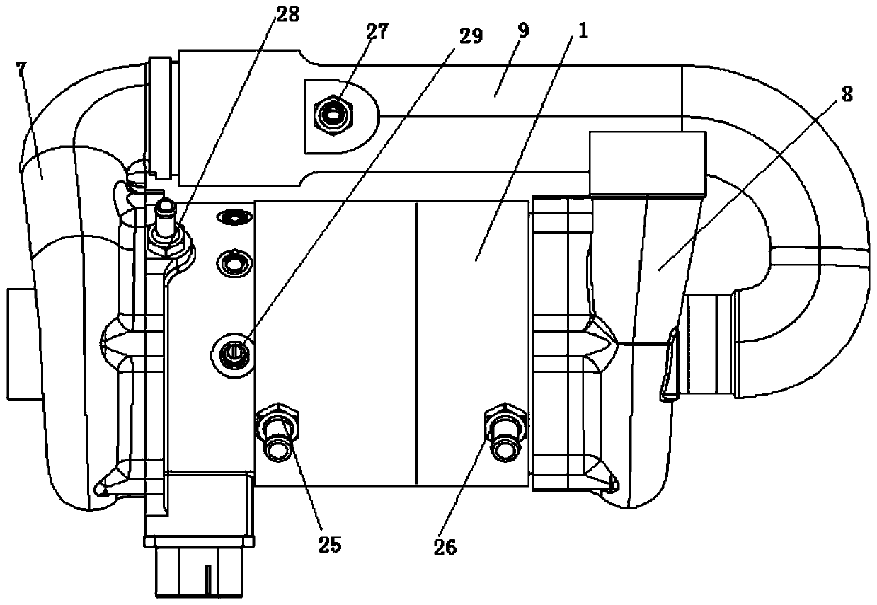
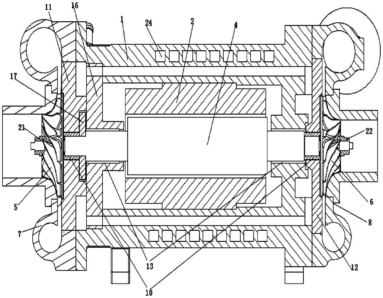
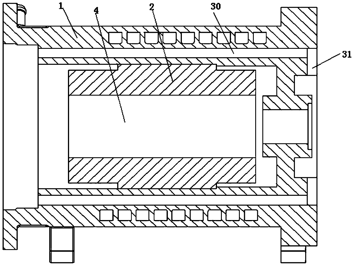
[0032] see Figure 1-4 , the present invention provides a two-stage air-suspension centrifugal electric direct-drive air compressor, which includes a housing 1, a motor stator 2, a main shaft 4 arranged in sequence from outside to inside, impellers, lock nuts and The volute is a cooling system arranged on the casing 1 .

[0033] The two ends of the casing 1 are respectively sleeved with a primary volute 7 and a secondary volute 8, the primary volute 7 and the...


PUM


Abstract

The invention discloses a two-stage air-suspending centrifugal electric direct drive air compressor. The two-stage air-suspending centrifugal electric direct drive air compressor comprises a shell, amotor stator, a spindle, impellers, lock nuts, volutes and a cooling system, wherein the shell, the motor stator and the spindle are sequentially arranged from outside to inside, the impellers, the lock nuts and the volutes are arranged on the two sides of the spindle, and the cooling system is arranged on the shell. The two-stage air-suspending centrifugal electric direct drive air compressor hasthe beneficial effects that the shell, the motor stator, the spindle, the impellers and the volutes are integrally designed, and the size and the weight of the whole machine are reduced. The two stages of impellers are connected in series through a middle pipeline, and small flow and the high-pressure ratio are achieved. Axial thrust of the two stages of impellers can be mutually offset, and axial force applied by thrust bearings is reduced. Radial and axial air bearings are adopted, gas films are formed through high-pressure gas generated by the bearings, friction between the bearings and arotor is reduced, air-suspending motor high-speed direct drive is formed, and mechanical losses are reduced. Part of compressed gas is introduced into a machine shell assembly through the middle pipeline, the motor stator, the spindle, the radial bearings and the thrust bearings are cooled, and the service life of the air compressor is prolonged.

Description

technical field [0001] The invention relates to the technical field of hydrogen fuel cell engines, in particular to a two-stage air suspension centrifugal electric direct drive air compressor. Background technique [0002] At present, the development of new energy fuel cell vehicles is considered to be an important link in the transformation of transportation energy and power, and has attracted much attention. Proton exchange membrane fuel cell is the most mature representative of the current fuel cell family. It is a device that uses hydrogen and air (oxygen in the air) as fuel to undergo an electrochemical reaction, and converts the chemical energy of the fuel directly into electrical energy, and the reaction generates water. It has the advantages of no pollution, high efficiency, wide application, low noise, quick start at room temperature, quick energy replenishment and modular structure, and is likely to become one of the main power sources of automobiles after the tra...

Claims


Application Information

Patent Timeline
Patent Type & Authority Applications(China)
IPC IPC(8): F04D17/12F04D25/06F04D29/056F04D29/28F04D29/42F04D29/58F04D29/66
CPCF04D17/122F04D25/06F04D29/056F04D29/286F04D29/4206F04D29/5806F04D29/582F04D29/662
Inventor 张学锋李锐白江涛陶林丁铁华王海军
Owner 势加透博洁净动力如皋有限公司
Why Eureka
Try Eureka