A Microcurrent Cesium Ion Source

A cesium ion and micro-current technology, applied in the field of ion sources, can solve problems such as harsh conditions of use, short service life, and difficulty in controlling the current of the ion source, and achieve the effects of high cesium utilization, long life, and simple structure

Active Publication Date: 2020-11-10
UNIV OF ELECTRONICS SCI & TECH OF CHINA
View PDF2 Cites 0 Cited by
  • Summary
  • Abstract
  • Description
  • Claims
  • Application Information

AI Technical Summary

Problems solved by technology

In the existing research on the cesium ion source, the cesium ion source that has been applied has many shortcomings, such as: it cannot be exposed to the atmosphere, resulting in harsh conditions of use, it is difficult to control the current of the ion source, and its service life is short.

Method used


Image

  • A Microcurrent Cesium Ion Source
  • A Microcurrent Cesium Ion Source
  • A Microcurrent Cesium Ion Source

Examples


Embodiment 1

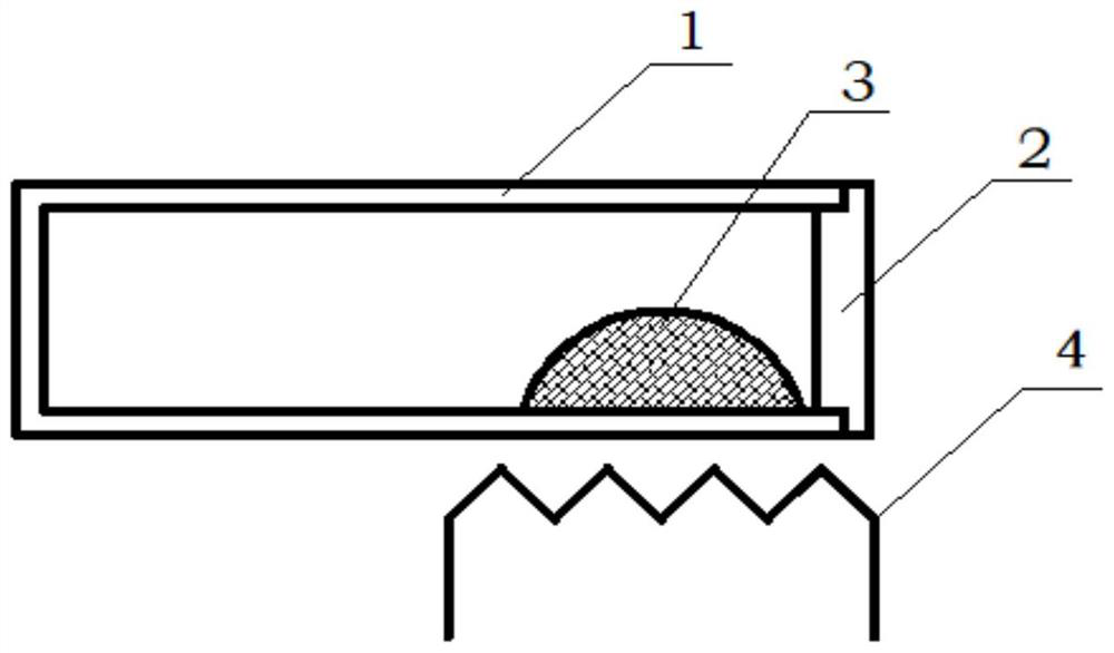
[0030] The present embodiment provides a kind of micro-current cesium ion source, such as figure 1 It includes a cesium storage body 1, a sealing cover 2, a cesium source 3 and a heater 4; the sealing cover 2 forms a vacuum-sealed container with the cesium storage body through vacuum sealing welding, and the cesium source 3 is installed in the vacuum chamber before welding. In the sealed container, the cesium source 3 can be elemental cesium or a cesium salt that is heated to generate elemental cesium. The heater 4 heats the vacuum-sealed container and the cesium source 3 to a high temperature state. The cesium salt generates elemental cesium at a high temperature, and the elemental cesium is passed through Heating and gasification forms cesium vapor, and gaseous cesium atoms diffuse through the top cover to the surface of the top cover and complete ionization on the surface to generate cesium ions.

[0031] In this embodiment, the sealing cover 2 is made of molybdenum materia...

Embodiment 2

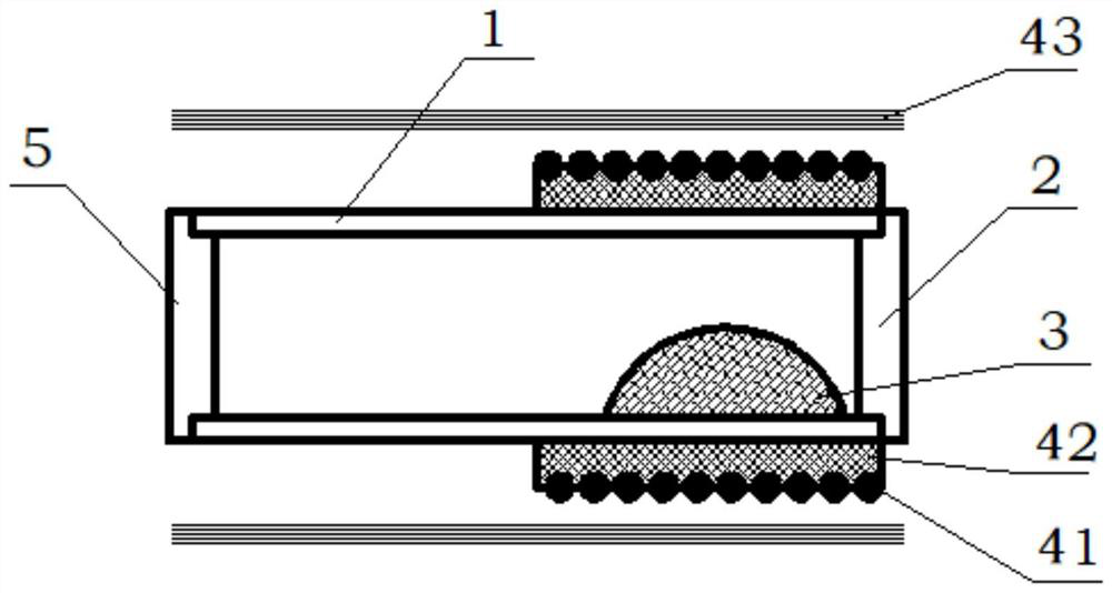
[0035] The present embodiment provides a kind of micro-current cesium ion source, such as figure 2 Shown includes a cesium storage body 1, a sealing cover 2, a cesium source 3, a heater 4 and a top cover 5. In this embodiment, the heater 4 is composed of a heating wire 41, an insulating ceramic 42 and a heat shield 43; the sealing cover 2 passes through Electron beam welding and the cesium storage body form a vacuum-sealed container, and the cesium source 3 is installed in the vacuum-sealed container before welding, and the heater 4 heats the vacuum-sealed container and the cesium source 3 to a high temperature state. The gaseous cesium atoms diffuse through the top cover to the surface of the top cover and complete ionization on the surface to generate cesium ions.

[0036] In this embodiment, the sealing cover 2 is made of molybdenum material through turning; the cesium storage body 1 and the top cover 5 are made of metal tantalum rod through turning;

[0037] In this embo...


PUM


Abstract

A microcurrent cesium ion source belongs to the technical field of ion sources. The ion source includes a cesium storage body and a sealing cover made of a material different from that of the cesium storage body. The work function of the material used for the sealing cover is higher than the ionization energy of cesium. The sealing cover is arranged to be joined with one end of the cesium storage body to form a vacuum seal. , the cesium ion source also includes a heater for heating the cesium source, the heater is arranged on the side close to the sealing cover, so that the cesium salt decomposes, the simple cesium gasifies, and the cesium atoms diffuse to the outer surface of the sealing cover through the sealing cover and on the outer surface Ionization creates a flow of cesium ions. The invention utilizes the diffusion effect of the cesium atoms in the sealing cover to continuously transport the cesium atoms to the outer surface thereof and draws the cesium ion flow based on the surface ionization. The invention provides a cesium ion source with adjustable current, exposure to the atmosphere and long service life, which not only reduces the requirements on the vacuum system, but also has the advantages of simple structure, convenient use and high cesium utilization rate.

Description

technical field [0001] The invention belongs to the technical field of ion sources, in particular to a microcurrent cesium ion source. Background technique [0002] Cesium ion sources have broad application prospects in material analysis, optoelectronic technology and other fields: [0003] In the field of materials analysis, metallic cesium (Cs) is often used as the primary ion for secondary ion mass spectrometry (SIMS) detection of those elements located at the right end of the periodic table. The SIMS technique generates analytical signals by bombarding a sample with a high-energy ion beam ("primary" ion beam), which "sputters" atoms from the sample surface. Each impact of 5-15keV primary ions emits a small number of atoms from the target surface. A small fraction of the emitted atoms are ionized upon emission and these "secondary" ions can be accelerated into a mass spectrometer and mass analyzed to yield information about the chemical and isotopic composition of the s...

Claims


Application Information

Patent Timeline
Patent Type & Authority Patents(China)
IPC IPC(8): H01J49/16H01J49/10
CPCH01J49/10H01J49/16
Inventor 祁康成陈闻斌何丰耘曹贵川王小菊
Owner UNIV OF ELECTRONICS SCI & TECH OF CHINA
Why Eureka
Try Eureka