
Sensorless control method and control system for internal permanent magnet synchronous motor

A technology of permanent magnet synchronous motor and control method, applied in control system, motor control, vector control system and other directions, can solve the problems of complex realization, large amount of calculation, nonlinear inverter and other problems, and achieve the effect of improving accuracy

Inactive Publication Date: 2019-11-12
NANJING YUEBOO POWER SYST CO LTD
View PDF4 Cites 6 Cited by
  • Summary
  • Abstract
  • Description
  • Claims
  • Application Information

AI Technical Summary

Problems solved by technology

However, this high-frequency voltage injection method and rotor position information extraction method are greatly affected by some practical factors, such as stator resistance, motor fundamental frequency, delay of digital control system, filter delay, crossover of dq axis flux coupling, inverter nonlinearity, etc.
[0004] For this reason, a method for detecting the rotor position and its error compensation in the low-speed section of the built-in permanent magnet synchronous motor based on the injection method of rotating high-frequency signals is proposed in the related art, and the influence of the filter and signal discretization on the position estimation accuracy is analyzed. It is proposed that in the low-speed section, a line segment can be used to fit the phase-frequency characteristic curve at the center frequency of the band-pass filter, and the relationship between the required compensation angle and the motor speed can be derived. Implementation is more complicated

Method used


Image

  • Sensorless control method and control system for internal permanent magnet synchronous motor
  • Sensorless control method and control system for internal permanent magnet synchronous motor
  • Sensorless control method and control system for internal permanent magnet synchronous motor

Examples


Embodiment Construction

[0032] Embodiments of the present invention are described in detail below, examples of which are shown in the drawings, wherein the same or similar reference numerals designate the same or similar elements or elements having the same or similar functions throughout. The embodiments described below by referring to the figures are exemplary and are intended to explain the present invention and should not be construed as limiting the present invention.

[0033] The position sensorless control method and control system of the built-in permanent magnet synchronous motor according to the embodiments of the present invention will be described below with reference to the accompanying drawings.

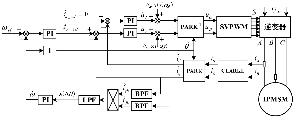
[0034] In the embodiment of the present invention, the built-in permanent magnet synchronous motor is controlled by using a speed-current double closed-loop structure.

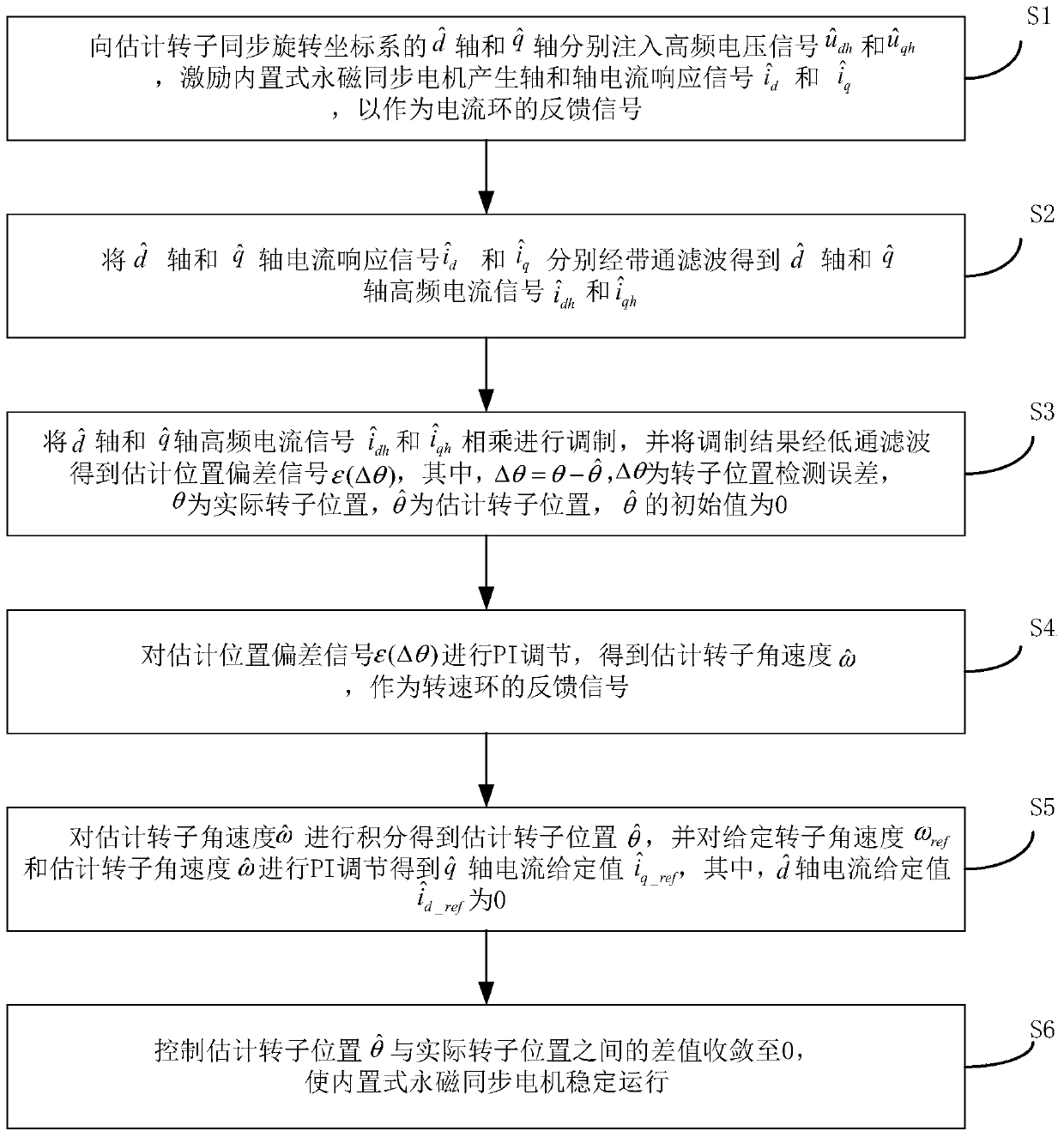
[0035] figure 1 It is a schematic flowchart of a control method for a built-in permanent magnet synchronous motor without a...


PUM


Abstract

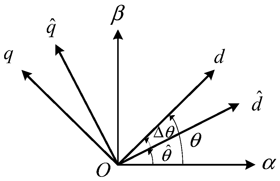
The invention provides a sensorless control method and control system for an internal permanent magnet synchronous motor. The method comprises the following steps: respectively injecting high-frequency voltage signals into shafts of an estimated rotor synchronous rotating reference frame, exciting the motor to generate a current response signal sum as a feedback signal of a current ring; enablingthe sum to obtain high-frequency current signal sum through band-pass filtering; multiplying the sum for modulation, and enabling the modulation result to obtain an estimated positional deviation signal epsilon(delta theta) through low-pass filtering; carrying out PI adjustment on epsilon(delta theta) to obtain estimated rotor angular velocity; carrying out integration to obtain estimated rotor position, setting rotor angular velocity omega ref and carrying out PI adjustment to obtain shaft current set value, wherein the shaft current set value is 0; controlling a difference value with actualrotor position to be converged to be 0 so that the motor operates stably. According to the control method, the influence of factors such as stator resistance and motor fundamental frequency can be reduced, and the accuracy of rotor position detection is improved.

Description

technical field [0001] The invention relates to the technical field of motors, in particular to a control method and a control system for a built-in permanent magnet synchronous motor without a position sensor. Background technique [0002] Built-in permanent magnet synchronous motors have been widely used in the field of new energy electric vehicles due to their small size, light weight, high power factor and efficiency, and superior control performance. In the control process, it is necessary to accurately obtain the rotor position information, which is often obtained by mechanical position sensors such as resolvers, which increases the volume, weight and cost of the system. In severe vibration and humid environments, such sensors are prone to failure. As people's requirements for automotive functional safety are increasing year by year, redundant control has been widely used in motor control systems in the new energy automotive industry to improve safety and reliability. ...

Claims


Application Information

Patent Timeline
IPC IPC(8): H02P21/24H02P21/18H02P21/00H02P25/022H02P21/22
CPCH02P21/0003H02P25/022H02P2203/11H02P2205/01H02P2205/07H02P2207/05H02P21/18H02P21/22H02P21/24
Inventor 蒋元广刘兵李占江高超李麟
Owner NANJING YUEBOO POWER SYST CO LTD
Learn More